Application of Siemens 840D CNC System in Gantry Boring and Milling Machine
When the position loop gain (Kv) of the CNC gantry boring and milling machine cannot be increased due to various reasons, a large following error and roundness error will occur during high-speed machining and circular interpolation, which will affect the machining accuracy of the workpiece. Without increasing the position loop gain (Kv), in order to reduce the machining error, we use the Siemens following error compensation function, also known as feedforward control, to improve the machining accuracy of the machine tool. This article mainly describes the speed feedforward control.
2. Working principleThe following error of the Siemens system generally refers to the difference between the position programming value and the actual value of the position loop, which reflects the dynamic following accuracy and static positioning accuracy of the machine tool. The relationship between following error and position loop gain is as follows:
E=V/Kv
Where: E-following error
V-Movement speed
Kv-position loop gain
It can be seen from the above formula that when the position loop gain (Kv) is determined, the following error is proportional to the movement speed, that is, the greater the speed, the greater the error. The position loop gain (Kv) of the CNC gantry boring and milling machine is affected by factors such as machine tool transmission rigidity and natural frequency, and its position loop gain (Kv) cannot reach a high value. Therefore, when high-speed machining, a large following error will occur and the machining accuracy of the machine tool will be reduced. Without increasing the position loop gain, in order to reduce the above error, Siemens provides the following error compensation function (Fllowing error compensation), also known as feedforward control (Feedforward control), through this function can reduce the following error to close to Zero, achieve the same effect of increasing the position loop gain. There are two types of Siemens feed-forward control, one is torque feed-forward control, the other is speed feed-forward control, most of which use speed feed-forward control. This article mainly discusses the debugging and optimization of speed feed-forward. Its working principle is shown in Figure 1:
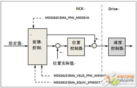
Figure 1 Speed ​​feedforward control
3. Effective way of following error compensation function:The effective mode of the following error compensation can be set to always effective through the parameter $MA_FFW_ACTIVATION_MODE or effective through program command selection, usually select effective through programming command selection.
Effective way of following error compensation:
MD32630 $MA_FFW_ACTIVATION_MODE = 0; feedforward control is always effective
= 1; Use the instruction to select whether it is valid in the program
Programming instruction: FFWON/FFWOFF following error compensation valid/invalid;
MD20150ã€23】=2 effective after channel reset
4. Parameter setting and optimization of following error compensation function:Note: Before using the following error compensation function, the position loop, speed loop, and current loop of each machine tool axis must be optimized!
1. Related parameters of following error compensation function
MD32610 VELO_FFW_WEIGHT
MD32620 $MA_FFW_MODE; Feed forward control mode 3: Speed ​​feed forward 4: Torque feed forward
MD32630 $MA_FFW_ACTIVATION_MODE; feedforward effective mode
MD32810 $MA_EQUIV_SPEEDCTRL_TIME; equivalent time constant of speed loop
2. Adjustment and optimization of the equivalent time constant of the speed loop
The only parameter that needs to be optimized and adjusted in the speed feedforward control is the speed loop equivalent time constant MD32810 $MA_EQUIV_SPEEDCTRL_TIME. The easiest way to adjust and optimize this parameter is to make the characteristic of the step response of the position loop, and use the servo trajectory to measure the difference between the given position value and the actual position value (especially the characteristic of 20μm before the actual position value reaches the target value. ), according to the positioning characteristics of the axis, adjust and optimize it to the best value. In order to obtain a good compensation effect, $MA_EQUIV_SPEEDCTRL_TIME must be accurately set in the machine data. The smaller the value, the stronger the effect of speed feedforward control.
1) Test procedure: (take X axis as an example)
In [Auto.] or [MDA] mode, choose to execute the following procedures:
FFWON
SOFT
LAB:
G01 X210 Fxxxx; The maximum feed rate of the axis
G04 F0.5
$AA_SCTRACE[X]=1; trigger for servo trace
X260
G04 F0.5
GOTOB LAB
M30
2) Test method
Use the servo trajectory function (Figure 2), select "Measure" and enter the measurement content (Figure 3), press the [NC Start] key, execute the program and measure according to the test curve (Figure 4), analyze the positioning characteristics of the machine axis, and adjust The parameter $MA_EQUIV_SPEEDCTRL_TIME.
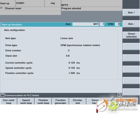
Figure 2 Servo trajectory
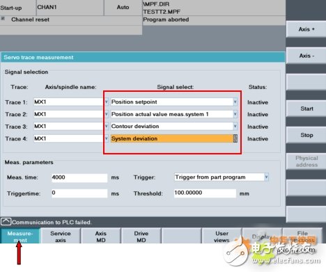
Figure 3 Measurement content
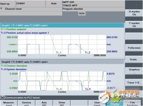
Figure 4 Test curve
3) Analysis and parameter optimization of the step response curve of the position loop: (take the X axis as an example)
When the speed feedforward is not effective, the actual position value, programmed value, contour error and system error of the measuring axis are measured, as shown in Figure 5:
MD 32620 $MA_FFW_MODE 0
MD 32810 $MA_EQUIV_SPEEDCTRL_TIME 0.0
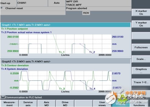
Figure 5 Test curve when feedforward is not effective
Activate the speed feedforward control to test the actual position value, programmed value, contour error and system error of the axis.
parameter settings:
MD 32610 VELO_FFW_WEIGHT 1.0
MD 32620 $MA_FFW_MODE 3
MD 32810 $MA_EQUIV_SPEEDCTRL_TIME 0.0025
MD 32431 $MA_MAX_AX_JERK 80
The test curve is shown in Figure 6. When the axis is positioned in a crawling state before moving to the target position, it means that the setting value of MD 32810 $MA_EQUIV_SPEEDCTRL_TIME is too large and should be reduced.
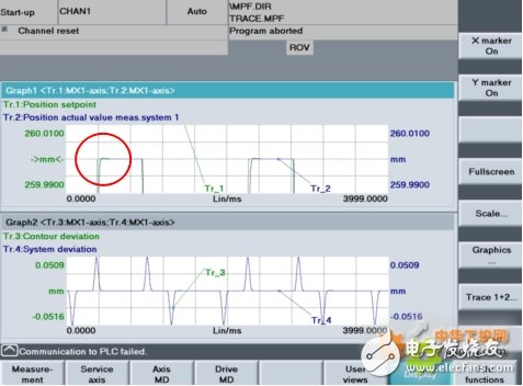
Figure 6 Response curve 1 when feedforward is in effect
parameter settings:
MD 32610 VELO_FFW_WEIGHT 1.0
MD 32620 $MA_FFW_MODE 3
MD 32810 $MA_EQUIV_SPEEDCTRL_TIME 0.0018
MD 32431 $MA_MAX_AX_JERK 80
The test curve is shown in Figure 7. When the axis moves to the target position, there is position overshoot phenomenon, indicating that the setting value of MD 32810 $MA_EQUIV_SPEEDCTRL_TIME is too small and should be increased.
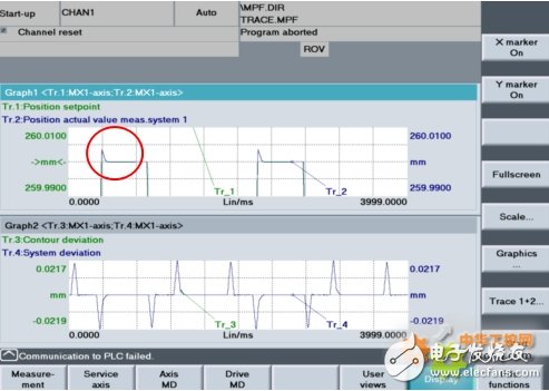
Figure 7 Response curve 2 when feedforward is in effect
parameter settings:
MD 32610 VELO_FFW_WEIGHT 1.0
MD 32620 $MA_FFW_MODE 3
MD 32810 $MA_EQUIV_SPEEDCTRL_TIME 0.002
MD 32431 $MA_MAX_AX_JERK 80
As shown in Figure 8: When the axis moves to the target position, there is no overshoot or crawling phenomenon, indicating that MD 32810 $MA_EQUIV_SPEEDCTRL_TIME is optimized to the best state.
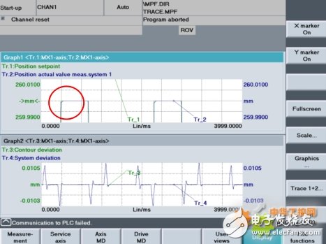
Figure 8 Response curve 3 when feedforward is in effect
According to the above steps, optimize the speed loop equivalent time constant of each interpolation axis of the machine tool one by one, and then take the maximum value of $MA_EQUIV_SPEEDCTRL_TIME for each interpolation axis and set it as the equivalent time constant of each interpolation axis speed loop.
Note: The above parameters of all interpolation axes should be set to the same value, otherwise the roundness will become ellipse when performing circular interpolation.
5. Roundness test:After the speed feedforward control is optimized and adjusted, the roundness test function needs to be used to analyze and evaluate the dynamic characteristics of the interpolation axis when the feedforward control function is in effect.
Example: Take the XY axis as an example
1. Test procedure
FFWON; activate feedforward control
SOFT
G17; select XY plane
G91; increment
G02 I10 J0 F5000 TURN=30; R=10mm V=5000mm/min Repeat 30 times
M30
2. Test results
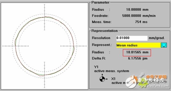
Figure 9 XY roundness test curve 1
After the feedforward control function takes effect, the actual radius of the circle will usually be too large when the roundness test is performed (as shown in Figure 9). This phenomenon can be done by adjusting the dynamic matching response time $MA_DYN_MATCH_TIME or the acceleration filter time constant MD32410 $MA_AX_JERK_TIME parameter Fix.
By optimizing the dynamic matching time constant, the roundness is corrected X Y
32200 POSCTRL_GAIN 3.2 3.2
32610 VELO_FFW_WEIGHT 1.0 1.0
32620 FFW_MODE 3 3
32810 EQUIV_SPEEDCTRL_TIME 0.002 0.002
32900 DYN_MATCH_ENABLE 1 1
32910 DYN_MATCH_TIME 0.0062 0.0062
Activate the dynamic matching function through the parameter $MA_DYN_MATCH_ENABLE, and optimally adjust the size of the $MA_DYN_MATCH_TIME dynamic matching time constant according to the results of the roundness test until the difference between the actual radius of the circle and the programmed radius is within the accuracy requirements, as shown in Figure 10:
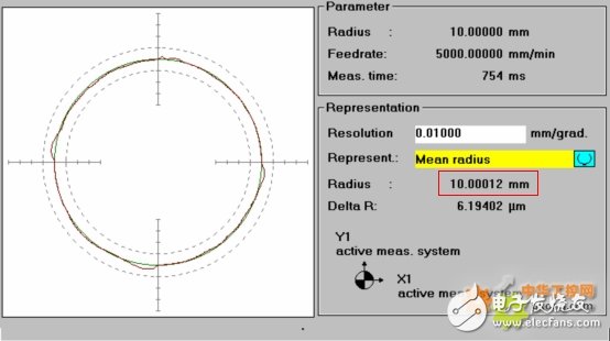
Figure 10 XY roundness test 2
The dynamic matching time constant $MA_DYN_MATCH_ENABLE of all interpolation axes should be set to the same value. If they are different, the circle shape will be affected, as shown in Figure 11:
X Y
32200 POSCTRL_GAIN 3.2 3.2
32610 VELO_FFW_WEIGHT 1.0 1.0
32620 FFW_MODE 3 3
32810 EQUIV_SPEEDCTRL_TIME 0.002 0.002
32900 DYN_MATCH_ENABLE 1 1
32910 DYN_MATCH_TIME 0.0035 0.0037
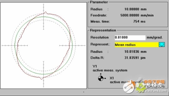
Figure 11 XY roundness test 3
Modify the size of the circle by adjusting the time constant MD32410 $MA_AX_JERK_TIME of the shaft impact limit filter
Activate the acceleration change rate time through the parameter $MA_AX_JERK_ENABLE, and select the acceleration change rate mode $MA_AX_JERK_MODE. It is recommended to use 32402 AX_JERK_MODE=2 to perform a power-on reset operation to activate the above settings. Execute the roundness test program, optimize the size of the parameter $MA_AX_JERK_TIME according to the test results, and adjust the actual size of the circle to within the required accuracy range. As shown in Figure 12:
X Y
32200 POSCTRL_GAIN 3.2 3.2
32610 VELO_FFW_WEIGHT 1.0 1.0
32620 FFW_MODE 3 3
32810 EQUIV_SPEEDCTRL_TIME 0.002 0.002
32900 DYN_MATCH_ENABLE 0 0
32400 AX_JERK_ENABLE 1 1
32402 AX_JERK_MODE 2 2
32410 AX_JERK_TIME 0.023 0.023
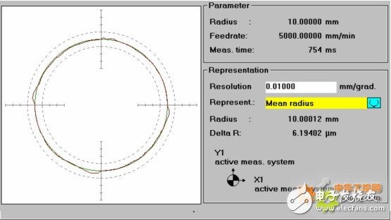
Figure 12 XY roundness test 4
If the time setting of the acceleration change rate of the interpolation axis is different, the circle shape will be affected, as shown in Figure 13:
X Y
32400 AX_JERK_ENABLE 1 1
32402 AX_JERK_MODE 2 2
32410 AX_JERK_TIME 0.023 0.025
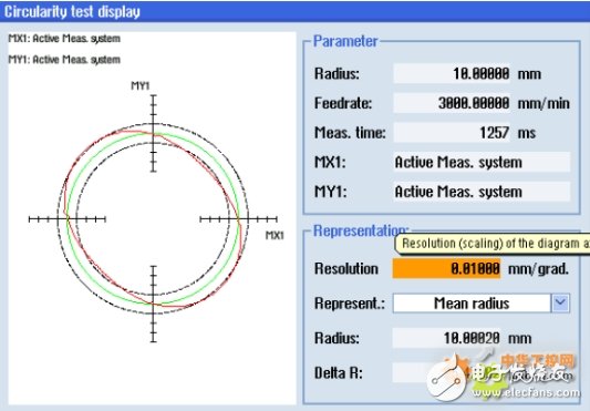
Figure 13 XY roundness test 5
6. Conclusion:By using the following error compensation function of the Siemens 840D CNC system, the 3x6m CNC fixed beam gantry boring and milling machine produced by our company can reduce the contour deviation by 0.03~0.05mm in the places where the acceleration changes such as arcs and corners when processing molds. The same effect of increasing the gain of the position loop is achieved, the processing quality is improved, and the precision and processing requirements of the machine tool are met.
Ic Diode,Diode Component,Ideal Diode Ic,Diode Array Ic
Shenzhen Kaixuanye Technology Co., Ltd. , https://www.icoilne.com
