Application of Video Fusion in Remote Control Robot System
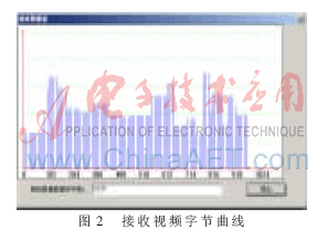
1 The overall structure of the system In view of the above situation, this article proposes to establish a standard coordinate system to make the simulation robot and the feedback video merge on the same interface. The simulation model previews the task and the feedback video tracks its trajectory to perform the operation. The robot is found in time by comparing the two. The operation situation will stop as soon as the violation of the rules and regulations occurs. The operator can also understand the scene environment according to the comparison of the two, such as the occurrence of obstacles or robot injury, immediately make the next order to avoid danger. The overall structure of the system is shown in Figure 1. Specific work flow: The video data collected by the camera from the real robot is sent to the static memory of the server-side image acquisition card for H.263 compression. The video data is compressed and transmitted to the client via the network. The client decompresses, restores, and displays the data, and displays the video on the simulation model interface to integrate the two. At the same time, the client implements the programming of the operation interface. The operation interface includes video fusion module, video processing module and control module. The video fusion module performs corresponding coordinate transformation on the video to make it coincide with the simulated robot and display it on one interface. The video processing module includes video zoom in, video zoom out, video save, open video, video screenshot, save bitmap, save JPEG image, open bitmap, open JPEG image and other functions. The simulation three-dimensional model is established by 3DSMAX, and it is drawn and controlled correspondingly in the OPENGL programming environment. The feedback video data is displayed on the client after compression, transmission, decompression, corresponding coordinate transformation and scaling. The server completes video collection, compression, storage, and transmission. The client completes simulation model control, decompression, video display, and corresponding zoom-in, zoom-out, screenshot, and save of the video. Because there is a delay in network transmission, and in addition to the fixed delay required to transmit the specified distance and the instruction execution delay, this delay also has some random disturbance delays. If this delay cannot be found in time, the operator Video feedback will make wrong judgments. According to this situation, a curve of the received data byte is drawn on the client, and the influence of the network condition on the video transmission can be visually observed, as shown in FIG. 2.


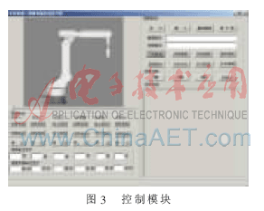
The control module is shown in Figure 3, including start and stop buttons for each joint, speed output, and speed variable output display.

2 Establishment of simulation model and realization of video fusion
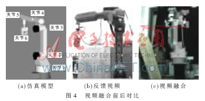
2.1 Communication establishment and video transmission Network communication is divided into synchronous mode and asynchronous mode. The synchronous method is a communication method in which the sender does not wait for the receiver to respond and then sends the next data packet; the asynchronous method is a communication method in which the sender sends the data and waits for the response from the receiver before sending the next data packet . This system develops client / server (C / S) structured software, which is an asynchronous non-blocking mode. The advantage of this mode is that it can be executed simultaneously or overlapped. When the image is transmitted in the network, it is inevitable to involve the transmission protocol. TCP / IP is a set of protocols, and the underlying protocols TCP and UDP play a vital role in the transmission of images. TCP is connection-oriented, that is, in end-to-end communication, the TCP protocol establishes a virtual circuit between end-to-end. UDP is a connection-free, it cancels the retransmission check mechanism, can achieve high communication efficiency, and is very suitable for data transmission with low reliability requirements. Because the robot system does not have high requirements for video frame loss, the client / server mode of UDP protocol is used. Video transmission adopts UDP transmission, establishes the Socket class to directly transmit image data, and the client calls the self-write show function to draw the feedback video in the OPENGL programming environment to achieve video reproduction. In the system, MFC is used to develop communication programs and operation interfaces. This is because MFC is mainly based on window and document application software programming. It integrates a large amount of data and methods, encapsulates many cumbersome tasks, such as application initialization, document processing and disk I / O, for user programming Brought great convenience. 2.2 Simulation robot model drawing After establishing the 3D simulation robot model of the MOTOMAN robot using 3DSMAX, the Deep ExplortaTIon conversion software is used to convert to VC code, and the OPENGL link library is added to the VC engineering settings to establish the project and call the converted simulation robot code. Stack operations are used when creating, loading, multiplying model transformations, and projection transformation matrices. In general, matrix stacking is often used to construct inherited models, that is, complex models composed of simple objects. In the MOTOMAN robot simulation model, a complex mechanical arm is composed of multiple simple cuboids based on the inheritance relationship, and this inheritance relationship is determined by the matrix stacking order. The mechanical arms, joints, and bases are scaled accordingly in proportion to the actual robot. After specifying the coordinate system of the base, other joints and arms can calculate the coordinate position and draw according to their three-dimensional dimensions. The robot model consists of 3 layers of supporting base, 4 rotating joints, 1 beam, 1 vertical column, claws and some other parts. The simulated robot model is shown in Figure 4 (a). Its inheritance is expressed when the end effector's claw moves (such as vertical ascent), first the joint 3 starts up, then the joint 2 rotates in the direction of the claw, then the joint 1 rotates slightly, and the entire robot translates vertically. Going down, the entire robot coordinated to keep the end effector (paw) upright. The display process of the three-dimensional model in OPENGL is: the three-dimensional objects in the world coordinate system are projected after three-dimensional geometric transformation, and then three-dimensional cutting and viewport transformation are performed, and finally the graphics are displayed in the screen coordinate system.

2.3 Video Fusion and Control Implementation After the viewpoint coordinate system of the simulation robot base is determined, the video robot scales and draws according to the size of the simulation robot so that the base and the simulation robot base are at the same coordinate position. The other parts of the robot in the video are mapped correspondingly as the base. Therefore, the joints and perspective positions of the video and the simulation model at the initial moment are basically coincident. The video fusion interface adjusts the video transparency through the VC control SLIDER. The operator selects the definition according to the actual situation, and can also set the feedback video to be completely transparent (at this time, you can only see the model and not the video). This simulation robot realizes the program control of 3DSMAX data model in OpenGL three-dimensional programming. 3DSMAX is a simple and fast modeling software, which has further improved the modeling function than similar software and more focused on the modeling of complex models. You can easily use C + + and OpenGL to realize the graphics algorithm, and then use this algorithm as a plug-in It is embedded in the 3DSMAX environment without considering the complex code of object model generation and processing. Using the 3DSMAX rendering timer can easily check the efficiency and effect of the algorithm [12]. In the production of simulated robots, one principle should be followed: as long as the visual effect can be guaranteed, a simpler model should be used as much as possible, and if the object that can be constructed by the parametric method should be constructed by the parametric method. At the same time, in the process of model creation, the model is divided and modeled independently to facilitate operation and inspection. The comparison of simulation robot video fusion before and after is shown in Figure 4. The control program realizes the simulation model control. The control process is: press the corresponding operation button, two threads run at the same time, one thread transmits the control instruction to the simulation model to make the virtual robot move, and the other thread transmits the control command to the network. The server controls the real MOTOMAN robot to complete consistent operations. In the simulation model and video fusion interface, the trajectory of the model is marked with a red line in the program (for the convenience of the observer, the red trajectory is drawn with a thick solid line of 10 pixels), the feedback video then tracks this trajectory, the operator Observe the operation of the robot in the video and determine whether the operation is up to the standard and decide the next step.
This video fusion method is applied to the teleoperation robot system, which can enable the controller to accurately judge the accuracy of the robot operation. At the same time, it combines traditional teleoperation robot video monitoring and simulation prediction, and proposes to apply video fusion to the teleoperation robot technology. The experimental results show that this method is very practical for robot systems with high accuracy requirements. In the future, this video fusion method can be extended to rescue and disaster relief, disaster situation investigation, project operation, water conservancy monitoring, and urban investigation. , Image transmission and other functions, you can also compare the difference between the forecast and the actual.
A flexible printed circuit board is a type of PCB designed to meet the needs of flexible electronic circuits. Originally designed flexible printed circuits to replace traditional wiring harnesses.
Flexible printed circuits are produced using flexible laminates. The flexible laminate holds the conductive foil as well as the dielectric substrate. Flexible circuit boards can be three-dimensionally routed and can be appropriately shaped to fit the available space.
Flexible PCB,Flexible Circuit Board,PCB Production Process,PCB Process Technology,Circuit Board Manufacturing Process
Huizhou Liandajin Electronic Co., Ltd , https://www.ldjpcb.com
