Automotive temperature control system connector circuit design strategy - circuit diagram reading every day (96)
With the rapid development and maturity of wireless communication and information sensing technologies, information sensing microcontrollers and networks are used to connect items into the Internet of Things to achieve the goal of automatic identification, positioning, tracking, relaying and management of items. It has become possible. The air conditioner in modern cars is generally controlled by hand. The air conditioner can only be turned on or off when the driver enters the cab. This makes people feel like when the air conditioner is not turned on when they enter the car in the hot summer or cold winter. To the abnormal heat or cold, the design and manufacture of equipment that can monitor the temperature inside the vehicle and perform remote control in advance according to the monitored temperature conditions to open the interior air conditioning system refers to the agenda of people's daily life. This design is Proposed to meet this requirement.
Temperature acquisition module
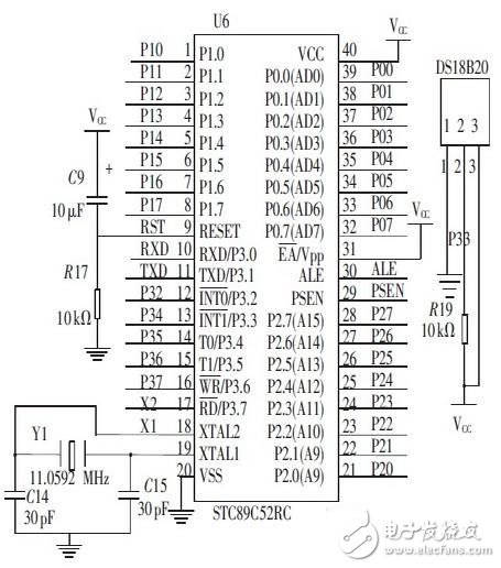
The temperature acquisition module in the system uses the high precision and high reliability DS18B20 temperature sensor produced by DALLAS. It has the characteristics of small size, low hardware overhead, strong anti-interference ability and high precision. It adopts single bus data communication and full digital temperature. Conversion and output, up to 12-bit resolution, accuracy of ±0.5 °C, detection temperature range of -55 ° C ~ +125 ° C, so it can meet the design requirements of this system. The connection circuit between the DS18B20 and the microcontroller is shown in Figure 2.

Figure 2 Connection circuit diagram of STC89C52RC microcontroller module and DS18B20
Relay switch control module
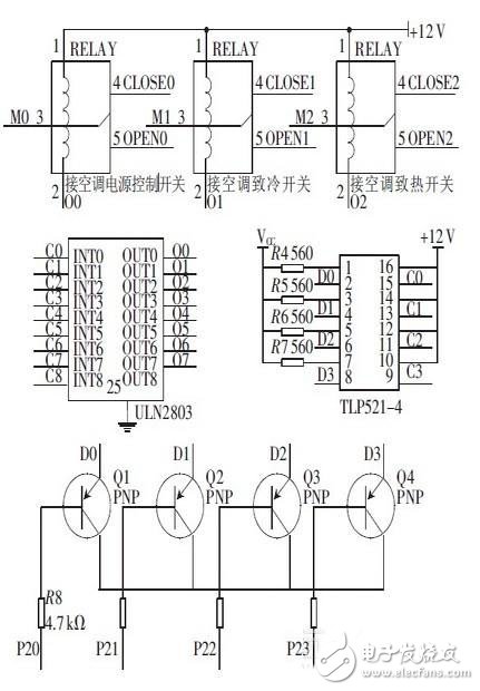
The relay switch module is composed of TLP521 -4 , ULN2803 and SRD -12VDC and triode. The signal output from the microcontroller is sent to the TLP521 -4 optocoupler chip through the triode switch circuit and then amplified by the ULN2803 Darlington tube. Drive the SRD-12DC relay to achieve the function of controlling various switches of the air conditioner. The circuit connection diagram of the relay switch control module and the microcontroller is shown in Figure 3.

Figure 3 relay control module circuit diagram
----------------------------------------
Force Sensor,Force Transducer,Strain Load Cell,Force Measurement Sensor
GALOCE (XI'AN) M&C TECHNOLOGY CO., LTD. , https://www.galoce-meas.com
