Characteristics and working principle of LCD
Characteristics and working principle of LCD
Liquid crystal display (LCD) is a very common display now. It has the advantages of small size, light weight, power saving, low radiation, and easy to carry. The principle of a liquid crystal display (LCD) is very different from a cathode ray tube display (CRT). LCD is a display device based on the electro-optic effect of liquid crystal. Including character display device in segment display mode; character, graphic and image display device in matrix display mode; large-screen LCD projection TV LCD screen in matrix display mode, etc. The working principle of the liquid crystal display is to use the physical characteristics of the liquid crystal to turn on when the power is turned on, so that the liquid crystal arrangement becomes orderly and makes the light easily pass; The following describes the working principle of the three LCD displays.
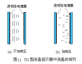
1. "Twisted Nematic Liquid Crystal Display" (Twisted NemaTIc Liquid Crystal Display), referred to as "TN-type liquid crystal display". The liquid crystal module structure of this display is shown in FIG. 11. The nematic liquid crystal is sandwiched between two pieces of glass. A layer of transparent and conductive film is first coated on the surface of this glass as an electrode. This thin film is usually an oxide of indium (Indium) and tin (TIn) (Oxide), referred to as ito. Then, the surface alignment agent is plated on the glass with ito, so that the liquid crystal is arranged in a specific direction parallel to the glass surface. (Figure 11a) The middle left glass aligns the liquid crystal in the up and down direction, and the right glass aligns the liquid crystal in the direction perpendicular to the drawing. The natural state of the liquid crystal in this component has a total of from left to right ![]() Distortion, which is why it is called a twisted LCD. Using the principle that the electric field can rotate the liquid crystal, applying a voltage to the two electrodes will cause the polarization direction of the liquid crystal to turn parallel to the direction of the electric field. Because the refractive index of the liquid crystal changes with the direction of the liquid crystal, the result is that after the light passes through the TN liquid crystal cell, its polarization will change. We can choose the appropriate thickness so that the polarization direction of the light just changes
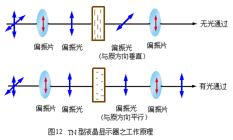
Distortion, which is why it is called a twisted LCD. Using the principle that the electric field can rotate the liquid crystal, applying a voltage to the two electrodes will cause the polarization direction of the liquid crystal to turn parallel to the direction of the electric field. Because the refractive index of the liquid crystal changes with the direction of the liquid crystal, the result is that after the light passes through the TN liquid crystal cell, its polarization will change. We can choose the appropriate thickness so that the polarization direction of the light just changes ![]() . Then, we can use two parallel polarizers to make the light completely unable to pass (as shown in Figure 12). If a sufficiently large voltage V is applied so that the direction of the liquid crystal turns parallel to the direction of the electric field, the polarization of light will not change. Therefore, the light can pass through the second polarizer smoothly. Therefore, we can use electric switches to control the brightness of light. This will result in white when light is transmitted and black when light is not transmitted, and characters can be displayed on the screen.
. Then, we can use two parallel polarizers to make the light completely unable to pass (as shown in Figure 12). If a sufficiently large voltage V is applied so that the direction of the liquid crystal turns parallel to the direction of the electric field, the polarization of light will not change. Therefore, the light can pass through the second polarizer smoothly. Therefore, we can use electric switches to control the brightness of light. This will result in white when light is transmitted and black when light is not transmitted, and characters can be displayed on the screen. 

2. Principle of TFT-type liquid crystal display The TFT-type liquid crystal display also adopts a design in which liquid crystal molecules are filled between two interlayers. It's just that the electrode on the left interlayer is changed to an FET transistor, and the electrode on the right interlayer is changed to a common electrode. In the design of the light source, the TFT display adopts the "back-through" illumination method, that is, the hypothetical light source path is not from left to right like TN LCD, but from right to left. This method is set on the back of the liquid crystal. Fluorescent tube similar to fluorescent lamp. When the light source is irradiated, it first passes through the right polarizer to the left, and uses the liquid crystal molecules to conduct light. Since the electrodes on the left and right interlayers are changed to FET electrodes and common electrodes, when the FET electrodes are turned on, the behavior of liquid crystal molecules will change as the TN liquid crystals are arranged, and the purpose of display is also achieved by shading and light transmission. But the difference is that due to the capacitive effect of the FET transistor, it can maintain the potential state. The liquid crystal molecules that have previously been transmitted will remain in this state until the FET electrode is powered on again to change its arrangement. Relatively speaking, TN does not have this characteristic. Once the liquid crystal molecules are not pressed, they immediately return to the original state. This is the biggest difference between the TFT liquid crystal and TN liquid crystal display principles.
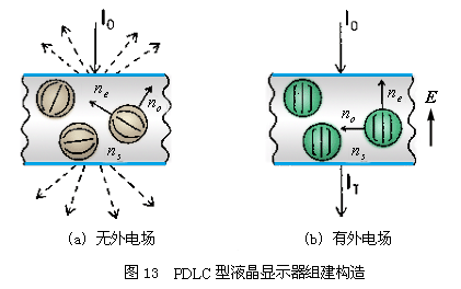
3. "Polymer dispersed liquid crystal display" (Polymer dispersed liquid crystal liquid crystal display), referred to as "PDLC type liquid crystal display". The structure of the liquid crystal module of this display is shown in FIG. 13. The polymer monomer (monomer) is mixed with liquid crystal and sandwiched between two pieces of glass to make a liquid crystal cell. This glass is the same as the one used above, with a transparent and conductive film coated on the surface as an electrode. However, no surface alignment agent needs to be plated on the glass. At this time, the liquid crystal cell is placed under an ultraviolet lamp to irradiate the monomers into a polymer. At the same time when the polymer is formed, the liquid crystal is separated from the polymer to form many small liquid crystal particles. These small particles are fixed by high molecular polymers. When light is irradiated on the liquid crystal cell, due to the different refractive index, refraction and reflection occur at the particle surface. After multiple reflections and refractions, scattering occurs. The liquid crystal cell is opaque and milky like milk. 
A large enough voltage is applied to the glass on both sides of the liquid crystal cell. The liquid crystal is aligned along the direction of the electric field, so that the arrangement of each liquid crystal is the same. For front incident light, these liquid crystals have the same refractive index n. If the refractive index of the polymer material we can choose is the same as n, these liquid crystal particles are the same as the polymer material for light; therefore, no refraction or reflection occurs inside the liquid crystal cell. The liquid crystal cell at this time is like transparent water.
Reel with double-skin flanges, in pressed steel with a turned drum. The external flange curl is suited for lifting through automatic hooks. The available sizes are as per DIN 46395 / 46397 specifications or as indicated by the Customer, for a normal use up to 1250 mm of flange diameter. This reel is dynamically balanced for speeds up to 60 m/s.
Indicated for metallic wires and cables.
To be used on a wiredrawing, stranding or rope-making machine. It withstands annealing treatment
| Serial Number | Specification Model | Lateral Plate Diameter D1 | Major Diameter D2 | Axle Hole Diameter D4 | Carrying Hole Diameter D5 | Center Distance E of Axle Hole and Carrying Hole | External Width L1 | Internal Width L2 |
| 1 | 400 | 400 |
224/250 280 |
125/127 | 28 | 100 |
265 300 |
224 250 |
| 2 | 500 | 500 |
280/315 355 |
125/127 | 28 | 100 |
300 375 |
250 315 |
| 3 | 560 | 560 |
315/355 400 |
125/127 | 28 | 100 |
355 425 |
280 355 |
| 4 | 630 | 630 |
355/400 450 |
125/127 | 28 | 100 |
375 475 |
315 400 |
| 5 | 710 | 710 |
400/450 500 |
250 | 40 | 170 |
425 530 |
355 450 |
| 6 | 800 | 800 |
450/500 560 |
250 | 40 | 170 |
475 600 |
400 500 |
| 7 | 1000 | 1000 |
560/630 710 |
250 | 50 | 250 | 750 | 630 |
| 8 | 1250 | 1250 |
710/800 900 |
250 | 50 | 250 | 950 | 800 |

Double Layer Wire Spools, Cable Spool, Steel Cable Reel,Steel Wire Drum
NINGBO BEILUN TIAOYUE MACHINE CO., LTD. , https://www.spool-manufacturer.com
