Design and Application of EMI Suppression of Driving Recorder Based on Clock Spread Spectrum Technology
This paper introduces the principle and classification of clock spread spectrum technology, combined with its specific application case in the camera, compared with the actual effect of traditional EMI suppression means, highlighting the advantages of clock spread spectrum technology in suppressing clock EMI. Currently, clock spread spectrum technology is widely used in industries such as image acquisition, image display, and automotive electronics.
I. Introduction
Clock is one of the main sources of electromagnetic interference energy. With the large-scale improvement of system design complexity and integration, the clock frequency of electronic systems is getting higher and higher; the application of traditional EMI improvement measures such as shielding and filtering has changed. More and more difficult, which prompted design engineers to explore more feasible and effective ways to reduce clock energy emissions, while the timely appearance of spread-spectrum clocks properly solved this problem and controlled and reduced from the source - system clock The EMI emission intensity. Currently, clock spread spectrum technology is widely used in industries such as image acquisition, image display, and automotive electronics.
Second, the principle
Spread spectrum technology reduces the peak energy and suppresses EMI by modulating the spike clock from a narrow-band clock to a spectrum with sideband harmonics, spreading the peak energy to multiple frequency segments in the spread spectrum region. Effect.
According to the frequency range of the modulated signal, the spread spectrum technology mainly has three modes: down-spreading, center-spreading, and up-spreading. Currently, the center spread spectrum is used to suppress EMI, and the center spread frequency ensures a more accurate average. frequency.
1. The time domain and frequency domain diagrams of the unmodulated periodic sinusoidal signal are as follows:
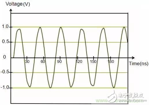
Figure 1 Time domain diagram of unmodulated sinusoidal signals
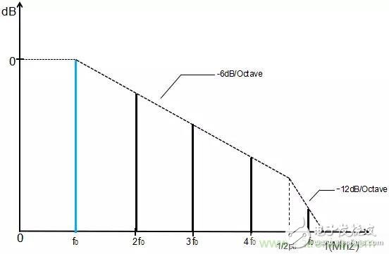
Figure 2 Frequency domain diagram of unmodulated sinusoidal signals
2. Use the spread spectrum technology to modulate the sinusoidal signal and extend the signal energy to a wider frequency.
In the rate range, the extended sinusoidal signal in the time domain and frequency domain is as follows:
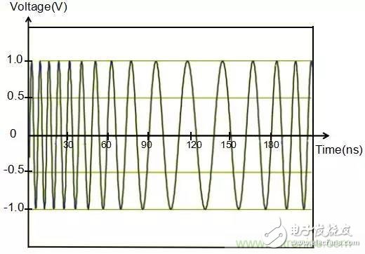
Fig. 3 Time-domain diagram after modulation of sinusoidal signal by spread spectrum technique
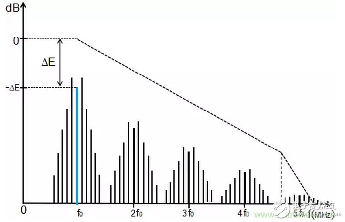
Fig. 4 Frequency domain diagram after sinusoidal signal modulation by spread spectrum technique
3. Actual effect diagram after using spread spectrum technology
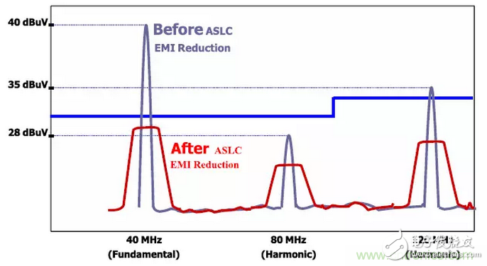
Figure 5 Comparison of actual effect diagrams before and after using spread spectrum technology
(1) The expansion rate is represented by d. It is used to measure the depth of clock expansion. It is the extension of the frequency domain. The frequency extension range is represented by Δf. The clock frequency before expansion is represented by fc, and the calculation method of Δf is
Δf= fc·d·100%
It is assumed that after the spread spectrum clock modulation, the percentage of the harmonic spectrum is fairly flat, and the peak energy suppression is approximately as follows
Where ASSC(i) - the clocked i-th resonant amplitude after the extended clock modulation;
ACLK(i) - the clock i-th resonant amplitude before the spread spectrum clock modulation;
RBW—Measures the bandwidth of electromagnetic interference energy.
Therefore, the calculation of electromagnetic interference that suppresses i-th harmonics is as follows
ASSC(i)·(dB)=ACLK(i)·(dB)-10log10(fc·d·100%/RBW)
The above formula shows that the higher the clock frequency, the better the spread frequency reduction effect; compared with the lower harmonics, the clock's higher harmonic spread spectrum has a better amplitude reduction effect.
Third, the advantages and applications of spread spectrum technology products
1, advantages
(1) Reduce costs
1 reduce the use of shielding materials, simplify the process and save labor costs;
2 Reduce the requirements for grounding. Ensuring that all data and clock signals return to the ground line produces electromagnetic interference emissions that meet measurement requirements are difficult. One solution is to add a ground plane, but this increases the cost of the board. However, spread spectrum clock technology can both suppress electromagnetic interference and reduce the requirements on the ground.
(2) Flexibility. The system can be designed as a non-spreading clock and a different proportion of spread spectrum clock, which can be freely switched by peripheral parameters.
(3) System-wide electromagnetic interference suppression. Other methods of electromagnetic interference, such as filtering, grounding, and shielding, can be used at specific locations to reduce electromagnetic interference at specific locations. In contrast, adding a spread spectrum clock reduces the electromagnetic interference of all signals synchronized with the clock.
2, application
Class A: Application of the clock source crystal oscillator
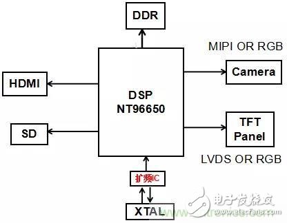
Figure 6 Schematic diagram of the spread spectrum IC used on the main clock
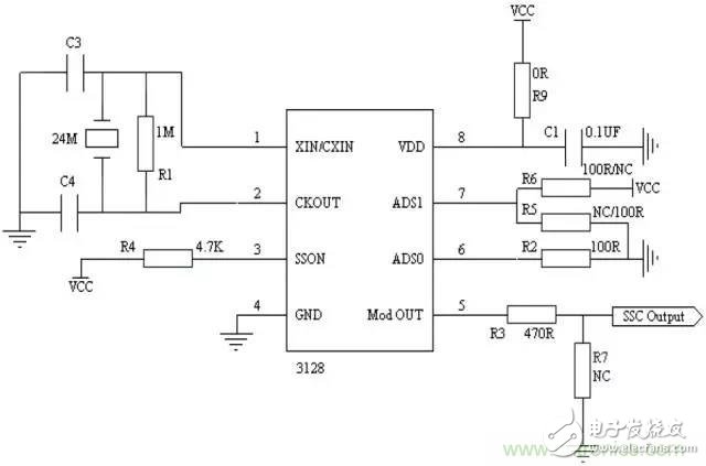
Figure 7 Spread spectrum IC used in the main clock circuit diagram
Description: Taking the driving recorder of the NT96650BG scheme as an example, after adding the spread spectrum IC to the main clock 24MHZ, the DDR clock, SD-CARD clock, camera clock, screen clock, etc., which are divided or multiplied from the main clock. Can get the corresponding spread spectrum, so that EMI is suppressed.
Class B: Application on CLK single line (take Sensor's MCLK as an example)
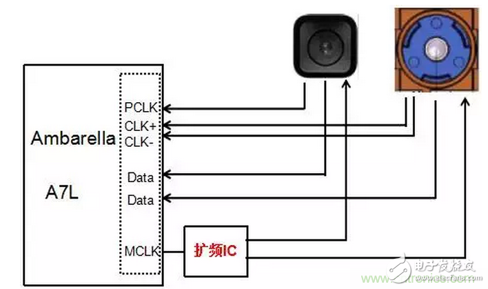
Figure 8 Spread spectrum IC used on a single-line clock
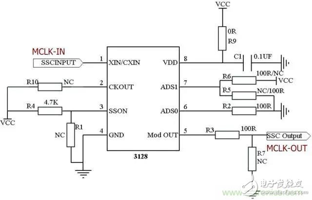
Figure 9 Spread Spectrum IC used in single-line clock circuit diagram
Note: Taking the IP camera of APA A7 as an example, due to the limitation of structure, the camera and DSP are generally in two different PCBs, and the middle is connected by cable. Therefore, the EMI problem of the camera is generally the difficulty of IPC radiation emission processing. Adding a spread spectrum IC to MCLK can suppress the harmonics of MCLK, and PCLK is also generated based on the MCLK clock, so the harmonics of PCLK can be suppressed accordingly.
Fourth, the case
A driving recorder uses the Aba A7 solution, and is equipped with the photosensitive chip of Magnesium AR0331; it is required to pass the EN55022 CLASS B radiation emission test standard, and it is powered by 12V battery during testing. There is no external accessories, the test data exceeds the standard, the specific test Data are as follows:
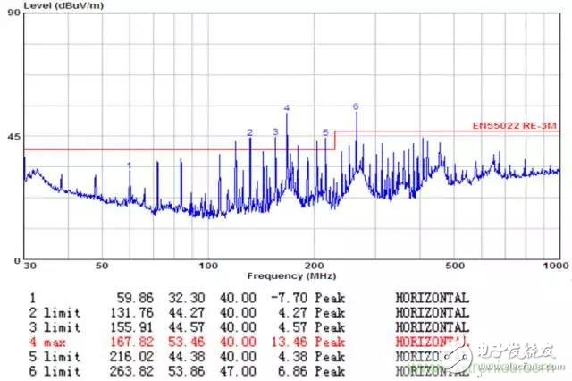
Figure 10 driving recorder for processing test data map
Data analysis (only the poor horizontal direction is listed): The product has a lot of frequency points between 30-1000MHZ, of which 168MHZ exceeds 13.46DB.
Radiation source analysis:
The product has two PCBs, including a motherboard and a small camera board. The two boards are connected by FPC cables. There is SENSOR CLK clock signal on the cable, MCLK clock frequency is 24MHZ, PCLK clock frequency is 48MHZ, if the camera test is turned off, the machine can pass the test standard; and the over-standard frequency point passes the test data analysis, most of which are 24MHZ times. Frequency, therefore, the MCLK and PCLK of the camera are determined to be the main source of radiation, and the whole structure is as follows:
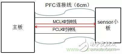
Figure 11 Product PCB connection diagram
Fourth, the rectification plan
1. Using conventional measures, add a smooth curve bead of 220R in series with MCLK and PCLK close to the source of the radiation, and add 22PF capacitor to the ground, as follows:
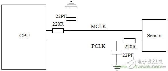
Figure 12 Schematic diagram of processing on the CLK clock line
Test data after processing:
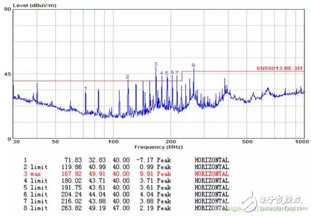
Data analysis: The overall has a certain decline, but there are still many over-standard frequency points, especially the 168MHZ is also exceeding the standard of 9.91DB, the effect is not satisfactory.
2. Add the spread spectrum IC to the CPU on the MCLK. No changes are made on the PCLK. The specific operations are as follows:
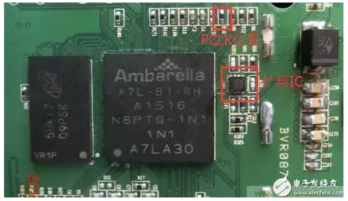
Figure 14 Adding a Spread Spectrum IC Physical Map to MCLK
Test data after processing:
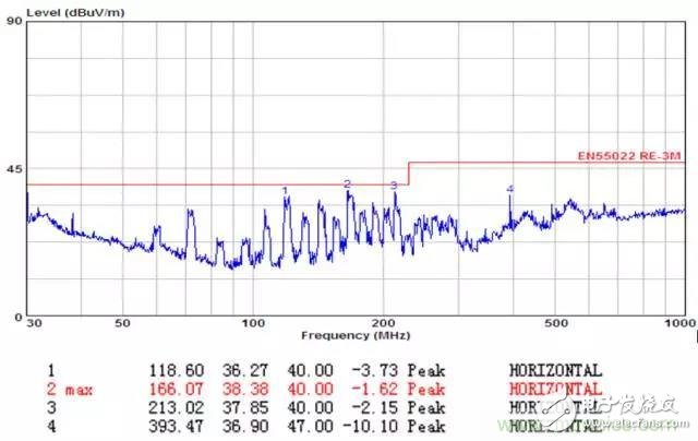
Figure 15 Test data graph after using spread spectrum IC on MCLK
Data analysis: The effect is obvious, the overall decline is 10-15dB, and the higher the frequency, the better the effect. After the rectification, the EN55022 CLASS B test standard can be passed, and the PK value margin exceeds 1.6DB.
Conclusion
The application of clock spread spectrum technology in suppressing clock EMI can simplify EMC countermeasures to a certain extent, reduce the cost of expensive shielding materials, and enhance the consistency of mass production of products. Therefore, when designing EMC in the initial stage of product design, Consider the compatibility design of the spread spectrum circuit to prevent the product from being damaged due to EMI rectification difficulties before the market, and miss the best market opportunity!
Household Electrical Appliances
gree , https://www.greegroups.com
