Design of multifunctional vehicle terminal based on SOPC technology
1 Introduction
This article refers to the address: http://
The vehicle navigation monitoring terminal can be widely used in traffic police patrol cars, fire-fighting vehicles, public security vehicles, money-carrying vehicles, long-distance buses and some special vehicles. The monitoring center communicates with the vehicle navigation monitoring terminal through the wireless communication network to realize monitoring. The center's centralized, efficient, visual management of vehicles and mutual cooperation between vehicles.
This design system analyzes the various functional requirements of the vehicle navigation monitoring terminal. With the rich logic resources of the Altera StratixTM series FPGA EP1S10, the SOPC Builder development tool is used to realize the high integration of the hardware structure of the vehicle navigation monitoring terminal. At the same time, the powerful processing power of the Nios embedded processor and the C/OS-II real-time operating system are used to realize real-time and efficient processing of various sensing information by the terminal.
2 Functional Description
The vehicle navigation monitoring terminal mainly realizes the detection, processing, display and wireless transmission and reception of various sensing information. Specifically include:
Wireless data communication module - realizes the exchange of instructions and data transmission between the monitoring center and the vehicle navigation monitoring terminal; the text information synthesis module converts the text information into voice information, and facilitates the terminal to obtain various commands and instructions of the monitoring center; GPS positioning Module - Get the longitude and latitude information of the terminal, the monitoring center can accurately understand the geographical location of the terminal on the electronic map; the video image acquisition module - obtain the specific situation inside and outside the car, can image information through the wireless network Transfer to the monitoring center; human-computer interaction module - display electronic map, various status information, collaborative status information and receive key input information; information storage module - for saving status and setting information; status detection and Control module - realizes the detection of the state of other equipment on the vehicle and controls the related equipment according to the command of the control center; the power management module - realizes the charging of the power source and the switching of the standby power source.
3 N ios soft core and peripheral module interface design
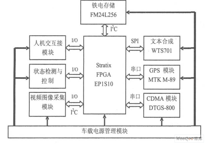
The high-performance, high-capacity StratixTM FPGA and the IOS embedded soft-core processor from Altera enable flexible configuration of the processor and peripheral interfaces, greatly advancing the SOPC (Programmable System-on-Chip) design process. At the same time, the SOPCBuilder visual development tool provided by Altera provides efficient configuration of hardware systems according to customer needs. Based on the N ios embedded soft core processor, the application of SOPC technology to design the vehicle navigation monitoring terminal will greatly simplify the complexity of the hardware design, realize the high integration of the terminal system, and meet the adaptation requirements of various interfaces. The block diagram of the multi-function vehicle terminal system based on EP1S10 is shown in Figure 1.

Figure 1 Multi-function vehicle terminal system block diagram
In the design of the terminal system, the modular design concept is adopted. Through the analysis of the functions of the vehicle terminal, the key functional modules required by the system are determined, and the interface between the function module and the EP1S10 is standardized. In the system block diagram, the CDMA wireless communication module and the GPS positioning module are connected to the EP1S10 through the serial port; the WTS701 text synthesis module is connected to the EP1S10 through the SPI-master bus; the FRAM information storage module is connected to the EP1S10 through the I2C bus, and these interfaces are in the SOPC Bu. Ilder's communication tool directory is available as a free IP core. In addition, the human interface module involves display and keyboard, which needs to be processed by I/O to define the timing control bus. The video image acquisition module needs a more complicated logic control interface to implement. The module design is introduced below.
The video image acquisition module consists of SAA7111 and ZR36060. The StratixTM FPGA controls the SAA7111's working status through the corresponding interface and acquires the digital video data compressed by ZR36060. The SAA7111 is a powerful programmable video input processing chip that decodes analog composite full-TV signals of different formats such as PAL and NTSC output from the camera into luminance and chrominance signals.
The output digital video signal format is available in 411YUV (16), 422YUV (12-bit), 422YUV or CCIR-656 (8-bit), 565RGB (16-bit), and 888RGB (24-bit). A variety of synchronization signals such as pixels, clock signals, and line fields are also provided. All of its programmable functions are done via the I2C bus to the corresponding control locations of the 32 internal registers, and the StratixTM FPGA's I2C interface can be easily programmed and controlled.
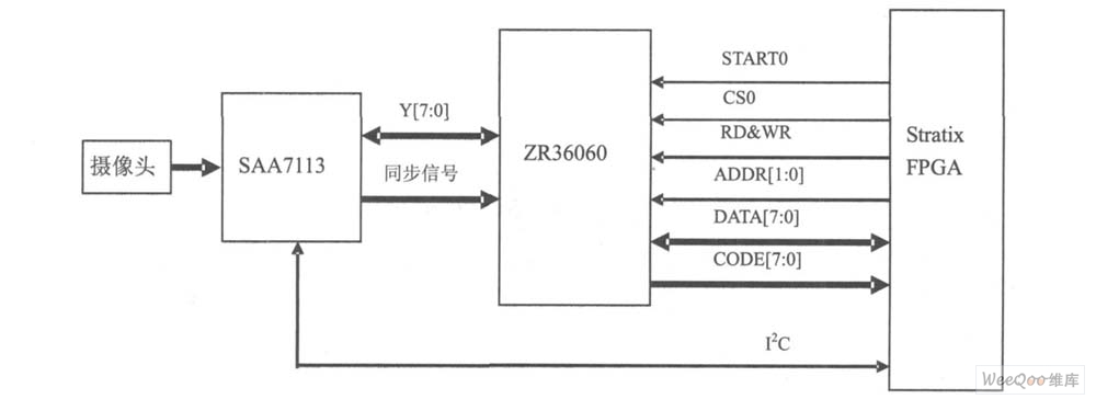
ZR36060 mainly completes the compression of digital video images and outputs files in standard JPEG format. Compressed data can be output from the compressed data port in a master mode or in a slave mode from the control port. Both modes have a handshake function for data flow control, which can be seamlessly integrated with the SAA7113. The interface between the StratixTM FPGA and the video image acquisition module is shown in Figure 2.

Figure 2 Interface between StratixTM FPGA and video image acquisition module.
The video image compression module ZR36060 works in the 16b it code width slave mode. The Stra tixTM FPGA can control the operation of the four video image compression module by using different chip select lines and startup conversion lines. The two I2C buses cooperate with the IICSA pipe angle of the SAA7113 to set the working state of the four-way image acquisition module. To achieve normal operation of the image acquisition and compression module through the S trat ixTM FPGA, it is necessary to design a reasonable interface control logic based on the ZR36060 interface timing diagram. The interface timing of the ZR36060 is shown in Figure 3.
In the SOPC development tool, the parallel input/output module (PIO) is called to construct a logical interface for operating the image compression module, and the Nios embedded soft core can use the logical interface to save the compressed image data in the SDRAM. At the same time, the correct setting of the working status of the SAA7113 and ZR36060 modules can be realized. 
Figure 3 ZR36060 passive mode interface timing
4 software system design
Once the system is designed, you can use the SOPC Buerder's System Generation page or use the command line to generate the system. The SOPCBuilder software automatically generates all the necessary logic to integrate the processor, peripherals, memory, bus, arbiter, IP core, and interfaces to the extra-system logic and memory, and to build HDL source code that bundles the components together. .
SOPC Builder can also build Software Development Kit (SDK) software components, which include INC, LIB, and SRC directories, which include header files, general peripheral drivers, custom software libraries, and real-time operating systems (RTOS). Kernel) to provide a complete design environment when building the system.
With the SDK software development kit, you can call the driver of the peripheral device as needed to develop the system software. The system software can be edited by various editing tools. After editing, start the ios SDK She l, l enter the nios-bu ild command and the corresponding source file name after the [ SOPC Bu ilder]$ command character. Compile, if there is an error, you can re-edit and then compile. For multiple source files, you can use the makefile command to compile. At this time, you need to create a special source file containing the entire project ( . c, . h,.
s) directory, and you need to modify the relevant options of the makefile.
The vehicle navigation monitoring terminal software includes a plurality of functional modules, which are linked to the embedded real-time operating system in the form of tasks. The specific functional modules are shown in Figure 4 below.

Figure 4 Car navigation monitoring terminal software function module
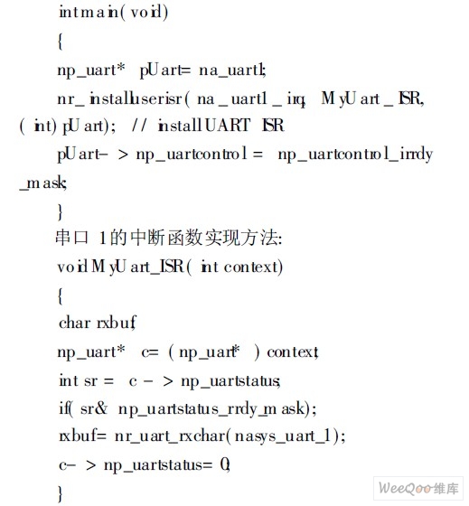
When using the underlying driver for each module, first set some variables and install the corresponding interrupt function. When using serial port 1 to control the CDMA module, the initialization process includes:
Serial port 1 interrupt function implementation method:

5 Conclusion
Based on the rich logic resources of StratixTM FPGA, the N ios embedded soft core is used to develop the vehicle navigation monitoring terminal using SOPC design technology, which greatly improves the design flexibility and optimizes the system structure.
Pmic Hot Swap Controllers,Pmic Hot Swap Controllers Ec-Mart,Management Pmic Hot Swap Controllers,Hot Swap Voltage Controllers
Shenzhen Kaixuanye Technology Co., Ltd. , https://www.icoilne.com
