Design of U disk audio player based on STC12C5A60S2
Abstract A U disk audio player based on STC12C5A60S2 is designed. The design idea and principle block diagram of the player are introduced. The specific implementation circuits are given for the three modules of the player, and the software program flow chart is provided. The running results show that the player achieves the expected function and has high cost performance and scalability.
A USB flash drive is a medium that uses flash memory for data storage, usually using a USB plug. The U disk is small, lightweight, hot swappable, and can be written repeatedly. Since its introduction, it has rapidly spread and replaced traditional floppy disks, becoming the main portable storage model. As the volume of the U disk continues to decrease and the storage capacity continues to increase, the range of use of the U disk continues to expand. However, the data stored in the USB flash drive is still mostly extracted and processed by computers, which limits the development of the USB flash drive.
The author believes that for a specific function, the dependence of the corresponding data on the computer is stripped off. On the one hand, the U disk data can be fully utilized, and on the other hand, the versatility of the USB protocol is exerted, so that the U disk can realize the portable characteristics obtained. Based on this, the U disk MP3 player circuit is designed, which mainly completes the data extraction and function running tasks of the audio files stored in the U disk. The player is equivalent to the audio processing module of the personal computer, and can not only recognize and extract the files in the MP3, WMA or MIDI format stored in the U disk, but also complete the data processing such as audio decoding by itself, and finally send it to the speaker or the earphone for playing. .
1 player composition block diagram
The composition principle of the player is shown in Figure 1. It consists of three main modules: The MCU processing module consists of STC12C4A60S52 MCU and its peripheral circuits; U disk read/write module consists of CH375 and its peripheral circuits; It is an audio decoding module. It consists of the VS1003 chip and its peripheral circuits.
The working process of the player is: The MCU reads the data from the USB storage device through the CH375, and according to the control command of the function key, sends the relevant data of the USB storage device to the audio decoding module, and after being decoded by the VS1003, is sent to the speaker or the earphone. . Set 6 personal computer interaction function buttons to realize basic operation functions such as play, pause, previous track, next track, increase volume, and decrease volume.
2 hardware circuit design
As shown in Figure 1, the circuit design of the three modules of U disk read/write, MCU processing and audio decoding is mainly completed.

Figure 1 schematic block diagram
2. 1 U disk read and write module
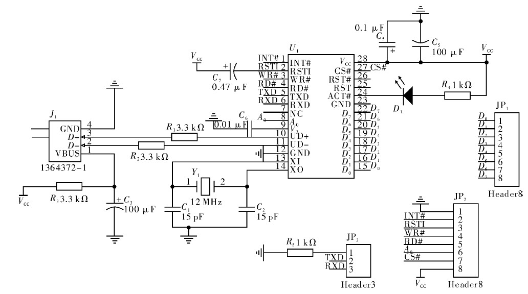
The U disk read/write module consists of CH375 and its peripheral circuits, and its composition is shown in Figure 2.

Figure 2 CH375 peripheral hardware circuit
CH375 is a USB bus universal interface chip that supports USB host and slave modes. On the local side, the CH375 has an 8-bit data bus and read, write, chip select control lines and interrupt outputs that can be easily hooked up to the system bus of the microcontroller/DSP/MCU/MPU controller. In USB host mode, the CH375 also provides serial communication, which is connected to the MCU/DSP/MCU/MPU through serial input, output and interrupt outputs.
The USB host mode of the CH375 supports common USB full-speed devices. The external MCU can communicate with the USB device through the CH375 according to the corresponding USB protocol. The CH375 also has firmware built into the dedicated communication protocol for Mass-Storage mass storage devices. External microcontrollers can read and write commonly used USB storage devices directly in sectors.
In the design, the CH375 adopts the host mode. In the figure, J1 is a USB socket, which can be connected to a storage device such as a USB flash drive. D1 is an indicator LED. When the connection of the USB device is detected, the light is on. When the TXD pin is connected to ground, CH375 works in parallel mode. At this time, JP1 interface D0 ~ D7 is a bidirectional data bus, which is connected to the microcontroller.
The JP2 interface in the connection diagram of the MCU is controlled by the program CH375. Its functions and characteristics are shown in Table 1.
Table 1 JP2 functions and features

The MCU controls the CH375 by writing commands and data, and obtains the U disk data through CH375. The CH375 has built-in firmware programs that automatically handle protocols such as USB. The MCU can directly obtain the data of the U disk sector through CH375, so the operation of the U disk file can be realized only by processing the FAT file system layer.
2. 2 MCU module
The MCU module consists of the STC12C4A60S52 microcontroller and its peripheral circuits. STC12C5A60S2 is a single clock/machine cycle single-chip microcomputer produced by Hongjing Technology. The instruction code is fully compatible with the traditional 8051, but the speed is 8 ~ 12 times faster. It provides 60 kByte of Flash program memory, 1 kByte of EEPROM, and integrates on-chip 1 280 Byte RAM. Voltage 5. 5 ~ 3. 5 V, internal integrated MAX810 dedicated reset circuit, 4 timers, 2 serial ports, 2 PWM, 8 high-speed 10-bit A/D conversion, ISP / IAP, built-in watchdog circuit, External brownout detection circuit, etc.
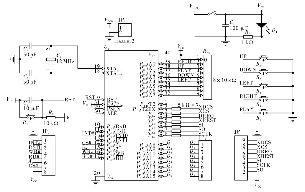
Figure 3 shows the hardware circuit diagram of the MCU module of the player. Among them, JP4 is the power input interface, D1 is the power indicator light, and the resistor Rp1 is the pull-up resistor of the P0 port. JP2 and JP3 are connected to the interface corresponding to the U disk read/write module. Since the MCU works under a 5 V power supply, and the VS1003 is under a 3.3 V power supply, the working P1 port should be connected to the current limiting resistor to JP1 and then to the corresponding interface of the audio decoding module. The circuit sets 5 function buttons, "UP" for increasing the volume, "DOWN" for decreasing the volume, "LEFT" for the previous song, "DOWN" for the next song, and "PLAY" for the play/pause button. .

Figure 3 MCU module hardware circuit
2. 3 audio decoding module
The audio decoding module consists of the VS1003 chip and its peripheral circuits. The VS1003 is a single-chip MP3 / WMA / MIDI audio decoder and ADPCM encoder. It includes a high performance, low power DSP processor core VS_DSP, working data memory, 5 kB of instruction RAM for user applications and 0.5 kB of data RAM, serial control and data interface, 4 general purpose I /O port, 1 UART, 1 high quality variable sample rate ADC and stereo DAC, 1 headphone amplifier and ground buffer.
The VS1003 receives the incoming bit stream through a serial interface and acts as a slave to the system. The input bit stream is decoded and then passed through the digital volume control to an 18-bit oversampling multi-bit ε-ΔDAC.VS1003 to control the decoder via the serial bus. In addition to the basic decoding function, other special applications can be made in the user RAM. , for example, DSP sound processing.
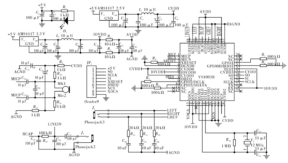
Figure 4 shows the VS1003 peripheral hardware circuit diagram of the player, where AVDD is analog positive power supply 3. 3 V, CVDD is digital positive power supply 2. 5 V, IOVDD is I / O positive power supply 3. 3 V, analog ground and The digital ground is isolated with a 0 resistor. J1 and J2 are both 3. 5 audio sockets, J1 is the audio output, and J2 is the audio input.

Figure 4 VS1003 peripheral hardware circuit
The MCU sets the VS1003 chip by writing to the VS1003 register, and writes data to the VS1003 data buffer for decoding.
3 software program flow chart
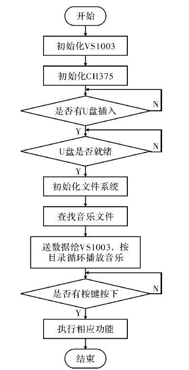
The MCU program mainly solves the problem of reading CH375 data and writing to the VS1003 register for playing music. Among them, the five functions correspond to the five function buttons of Figure 3 one by one. The software program flow chart is shown in Figure 5.

Figure 5 program flow chart
4 Conclusion
As shown in the figure, it aims to strip the audio processing function from the computer, expand the use range of the U disk, design the player circuit for the data processing of the U disk audio file, and write the related program in C language. The circuit is mainly composed of three modules, among which the main controller adopts the enhanced 51 single-chip STC12C5A60S2, the voice decoding chip adopts the VS1003 of the Finnish VLSI company, and the USB device interface chip selects the CH375 of Nanjing Yuheng Company, adopts the USB host mode, the external single-chip microcomputer You can read and write common USB storage devices directly in sector-based units without having to deal with the USB protocol.
The actual running results prove that the player fully meets the design expectations, and the U disk is plug and play, which can not only play MP3 files, WMA files, MIDI files in the specified directory of the U disk, but also realize various functions through button control. The overall system circuit is cost-effective and has strong scalability.
references:
[1]. CH375 datasheet http://+_1135273.html.
[2]. VS1003 datasheet http://+_696263.html.
[3]. MAX810 datasheet http://+_1019165.html.
Solar Power System Accessories
Solar Power System Accessories,Solar System Accessories,Solar Installation Kit,Solar Battery Kit
SUZHOU DEVELPOWER ENERGY EQUIPMENT CO.,LTD , https://www.fisoph-power.com
