Different specific connection methods of monitoring system points
Need equipment: network camera, hard disk recorder NVR (or ordinary PC plus client, suitable for home users with a small number of desktop computer installation), switches (according to the number of cameras and code rate adjustment, can be used by the supplier's recommendations) Hard disk, monitor, network cable, power cable, power adapter (or 12V DC switching power supply), camera bracket, cable crystal head.
Installation principle:
Front-end camera in the state of normal operation of power, through the network cable and the switch will be captured video signal to the background of the hard disk recorder for preview and storage. There are differences in the specific connection methods for the monitoring system points. The specific connection diagram can be seen in the following third step.
installation steps:
The first step is to determine the installation position and monitoring area of ​​the camera and fix the camera to the building or the pole frame through the camera bracket.
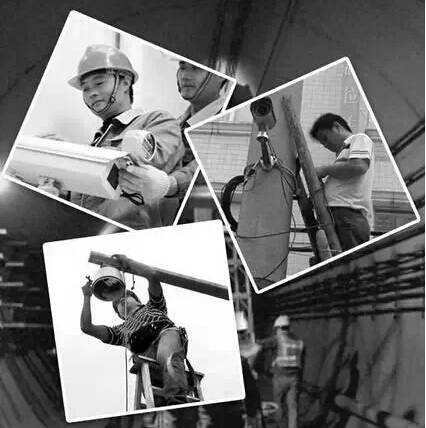
The second step is to determine the placement position of the back-end devices (hard disk recorders and monitors). The hard disk video recorder is installed and placed on the hard disk, and a power strip is prepared for the background devices.
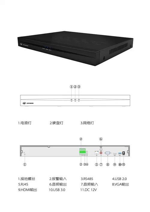
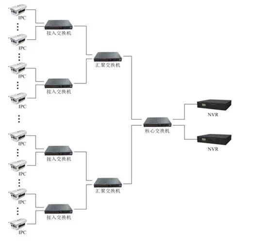
In the third step, after the front and back ends are completed, wiring is needed (if the planning or plan is done in advance, this step is actually prioritized, especially in the environment where the decoration is prepared, the pipeline needs to be embedded). There are two parts: First, to confirm the position of the switch, each camera must be connected to the switch through a network cable, and a network video recorder (NVR) must be connected to the switch. The cable should be routed according to the principles of convenient cabling, aesthetics, and security. , And in each network cable do two crystal head; Second, the camera power supply line wiring, each camera requires a 12V/1A or 2A power adapter, look at the construction environment or cost requirements, can be replaced with a switching power supply (recommended 12V/10A switching power supply should not bring more than 10 cameras, and so on, and need to be equipped with a power plug. In addition, depending on the number of points in the monitoring system, the connection method used is also different.
Architecture I: 1-8 points of minor works
For small projects of 1 to 8 points, you can directly use ordinary 100M switches to build the network environment. If 2 megapixel IPC is used and the code stream is calculated at 6 Mbps, the 8 cameras will occupy 8*6=48M of bandwidth, and the actual usage rate of the 100M switch will be 50%-70%, ie 50-70M, which can fully satisfy 8 IPCs. Transmission requirements.
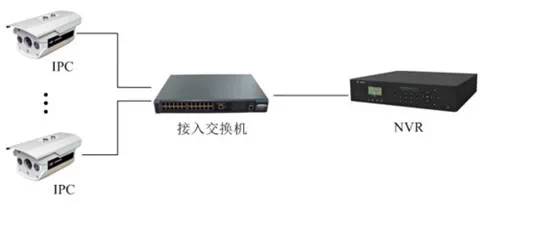
Architecture II: 9-50 points of small and medium-sized engineering
For small and medium-sized projects with 9-50 points, it is not enough to use only 100-megabit switches. Higher-performance second-tier full-gigabit switches are required for convergence to ensure smooth video information transmission.
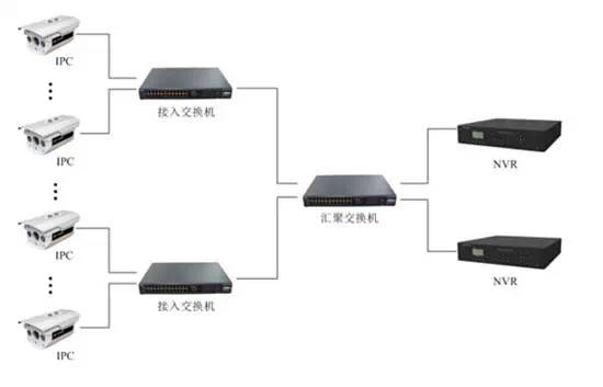
Architecture III: Medium to large projects of 50 points or more
For medium- and large-scale projects with more than 50 points, a three-tier network architecture is required: the access layer, the convergence layer, and the core layer. At the same time, because of the large number of points, the performance of the core-layer switches is relatively high. In this case, three-tier full-gigabit core switches such as Huawei or Huawei must be selected.
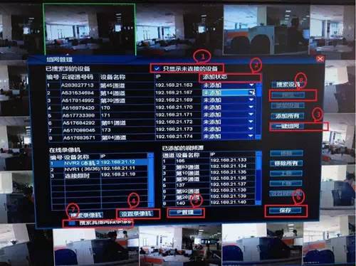
The fourth step is to debug the camera. After the installation is completed and all the lines are connected, the camera is powered on. The relevant network settings must be set on the network hard disk recorder (NVR), and the distribution network camera must be added. (The configuration methods vary from manufacturer to manufacturer.) ), After adding all the cameras, you will see the image, and you can debug the camera's angle, focus lens, etc. to the appropriate effect.
Precautions:
The relevant settings of the network DVR, video, image colors, etc., need to be set manually, and can be operated according to the instructions of the purchased device. Such a network monitoring system is completed.
USB Cable :1.Type A: almost every USB cable has a standard flat rectangular interface at one end. Most computers have a usb-a port to connect to only one USB port.
2.Type-B: almost square connector for printers and other active devices connected to computers. They are not common now because most devices have been moved to smaller connections.
3.Mini USB: a smaller connector type that was standard for mobile devices before micro USB. It's not common today, but you'll see it on some cameras, PlayStation 3 controllers, MP3 players, etc.
4.Micro USB: the current standard for mobile and portable devices, even smaller than Mini USB. Although you can still find micro USB on smartphones, tablets, USB battery packs and game controllers, some have turned to usb-c
5.Type-C: the latest USB standard, which is a reversible cable, promises higher transmission speed and higher power than previous USB types. It can also take into account a variety of functions.
USB Cable
ShenZhen Antenk Electronics Co,Ltd , https://www.atkconnectors.com
