How to plan the driving route of autonomous vehicles safely and effectively?
In fact, path planning technology is a very active research field at this stage. The reason why path planning is so complicated is that it covers all the technical fields of autonomous driving, from the most basic brakes, to sensors that perceive the surrounding environment, to positioning and prediction models, and so on. Accurate path planning requires the car to understand where we are and what actions the surrounding objects (other vehicles, pedestrians, animals, etc.) will take in the next few seconds. Another key technology is a trajectory generator, which generates a reference trajectory input to the path planning algorithm.
In this issue of algorithm sharing, we focus on introducing a highway path planning algorithm based on C++++. The algorithm uses jerk minimisation technology to generate a safe and efficient driving path in the simulator.
Some assumptions of this algorithm are as follows:
Under any circumstances, there will be no accidents with other vehicles
Maximum travel speed is 80KMH
The maximum acceleration is 10m/s2
Maximum jerk is 10m/s3
The vehicle does not exceed 3s between different lanes
Vehicles cannot exceed 3 lanes of high speed
The vehicle cannot drive in reverse
The functional layer of self-driving cars
First, let's study in detail the functional layers of autonomous vehicles (Functional Layers).
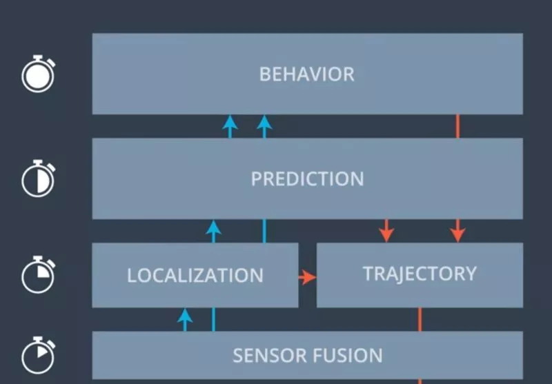
Path planning requires cooperation and coordination between different functional layers of autonomous vehicles. The figure above shows the configuration form of the functional layer of an autonomous driving system:
Action control layer: Responsible for controlling the car to make it follow the "set" trajectory form as much as possible. This layer needs the fastest response speed;
Sensor fusion layer: Responsible for merging the output of two sensors (such as radar and lidar)
Positioning layer: Responsible for locating the position of the vehicle on the map as accurately as possible, and calculating the position of other objects relative to the vehicle
Prediction layer: Responsible for identifying the nature of the object detected by the sensor (also known as perception), and predicting near-future changes in the scene based on the current trajectory of the car, the trajectory of other vehicles, and various elements in the scene (such as traffic lights). An important task of this layer is to predict conflicts.
Behavior layer: The main role of this layer is coordination. Decide how to adjust the driving trajectory according to the input information at the bottom layer
Trajectory layer: Responsible for calculating the driving trajectory under the established conditions (speed, distance, lane, jerk, etc.)
There are many ways to generate the driving trajectory, here we use the Frenet Coordiante System method.
The significance of the sensor fusion layer
We set up a series of sensors for the vehicle in the simulator, and their outputs are fused together to produce more accurate measurement results. Most self-driving car companies on Level 4 use radar, lidar, and cameras in their sensor kits. It is important to have many different types of sensors, because each type of sensor has its own advantages and disadvantages. In addition, redundant design for the same kind of sensors can reduce the impact of sensor failures.
In this algorithm, the simulator can provide the following sensor fusion functions:
The position, speed and direction of the vehicle
The position and speed of other vehicles
Vehicle trajectory submitted last time
Through the above information, we can calculate the accurate distance between the vehicle and other vehicles, and predict the possibility of collision with other vehicles through the driving trajectory.
Below we introduce Trajectory Generation in detail.
Frenet coordinate system
Usually, we are used to using the Cartesian coordinate system to define the position of a point in space. But in reality, roads are often not "straight". Therefore, very simple operations for humans (such as judging which lane the vehicle is in) are often difficult to accurately define in the Cartesian coordinate system of the computer. The following figure shows the problems we face when using the Cartesian coordinate system:
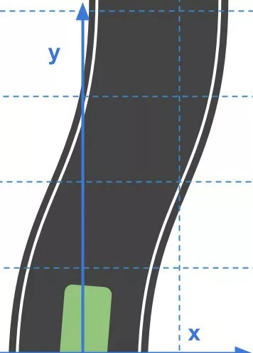
Curved lane in Cartesian coordinate system
Imagine that if the coordinate system we adopt can reflect the curvature of the road, then the trajectory of the vehicle driving forward and keeping in the lane under the new coordinate system will become a straight line, which will greatly simplify the difficulty of path planning. The Frenet coordinate system can realize our vision.
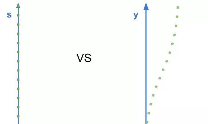
Driving trajectory in different coordinate systems:
Frenet (left) vs. Cartesian coordinate system (right)
In the Frenet coordinate system, the position of the point on the plane can be positioned by the vertical axis and the horizontal axis, which are denoted as S and D respectively. The mathematics behind it is very complicated, so we won't go into it here. You can think that the curve passing through the center of the road determines the S-axis and indicates how far the vehicle has traveled on the road; the D-axis is mapped to the lateral displacement of the vehicle. The following figure shows what a winding road looks like in the Frenet coordinate system:
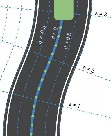
Smoothing of driving trajectory
We assume that the lanes have been pre-mapped and provide waypoints along the middle yellow line, which separates the two sides of the road. This helps us determine where we are on the closest waypoint.
Since the path points we set are very sparse, when we try to convert Frenet back to real-world coordinates, a trajectory with bent corners will be generated. This in turn will cause sudden acceleration and turbulence of the vehicle. Since the function toRealWorld(s, d) -> (x, y) uses linear interpolation between two path points to determine the best approximation values ​​of x and y, we always risk generating a non-smooth trajectory.
How to improve? In the previously shared algorithm, we found that the curve fitted by the polynomial tends to produce a very smooth trajectory. Therefore, we use polynomial fitting instead of linear interpolation. Use the position s in the Frenet coordinate system to create a spline, get the real world coordinates (x, y) and offset (dx and dy), and then substitute this formula to get the coordinate point closest to the real world.
x=spline_s_x(s)+d*spline_s_dx(s)y=spline_s_y(s)+d*spline_s_dy(s)
It can be seen that the optimized driving trajectory is very smooth.
State control mechanism
Another problem with path planning is that humans can switch cars to different states based on driving style, environmental information, and destination. It turns out that we can compile the state of rolling stock into a dictionary and instruct them to convert other layers of the autonomous driving system to which state based on the current state.
In the algorithm, our state control mechanism is very simple, as shown below:
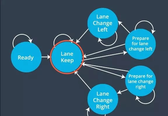
The final state control mechanism
The most common state is to keep the lane, but whenever we want to change lanes, the car will first transition to the left/right state where it is ready to change lanes, and make sure that it is safe to change lanes. The intermediate state entered before changing lanes is similar to the vehicle turning on the left/right signal before changing lanes.
Regarding the realization of the state machine, we got inspiration from the Frenet coordinates. We decompose a given state into its vertical and horizontal components. The vertical state represents keeping the current lane, the horizontal state represents the next state we may enter, and the cost function tends to choose the vertical state.
Loss function
Given that we usually return multiple candidate states and trajectories, we must find a way to choose the "best" course of action. We use a loss function to solve this problem. The loss function can teach the car the reasonable behavior we want and which behavior to punish with different weights.
All our cost loss functions follow the interface defined in the cost_functions file:
typedeffunction&,constTrajectory&,constState&,constdouble&)>CostFunction;
Final Results
It can be seen that the current path planner we have designed is running quite well, which can ensure that the vehicle runs safely and effectively in the lane. In the future, we plan to further optimize by adjusting the weights, improving the loss function, and adding machine learning algorithms to the prediction layer.
48V 100AH Powerwall Solar Battery
Shenzhen Jiesai Electric Co.,Ltd , https://www.gootuenergy.com
