Infrared camera solution based on LPC2138
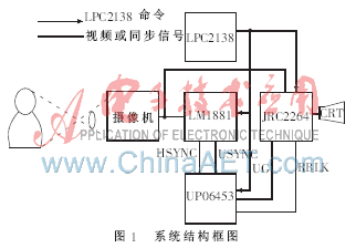
1 system hardware design based on LPC2138 ARM7 implementation of the infrared camera system block diagram shown in Figure 1, its main hardware includes LPC2138 LM1881, UPD6453, JNM2266, A3967 and so on.
This article refers to the address: http://
The LPC2138 is a 32/16-bit ARM7 TDMI-STM CPU microcontroller from PHILIPS with 512 KB of embedded high-speed flash memory. 128-bit wide memory interface and unique acceleration structure enable 32-bit code to run at maximum clock rate; multiple serial interfaces including 2 standard UARTs, 2 high-speed I2C interfaces; 9 edge or level triggered An external interrupt pin that implements a CPU operating frequency of up to 60 MHz with an on-chip PLL. The CPU operates from a voltage range of 3.0 to 3.6 V (3.3 V ± 10%) and the I/O port can withstand a maximum voltage of 5 V.
LPC2138 circuit diagram shown in Figure 2, mainly to achieve the following functions:
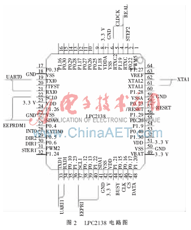
(1) Using the two serial ports of the LPC2138, one serial port can communicate with the host computer and the other can communicate with the camera. All protocol commands sent by the host computer are first analyzed by the LPC2138, and the PTZ is controlled or sent directly to the camera.
(2) Extend two EEPROMs with two I2C ports, one for storing Chinese character dot matrix codes for superimposing Chinese characters; the other for storing user setting information, such as watch position, preset position, patrol group data Wait.
(3) Using the LPC2138 an external interrupt to detect the zero-crossing point of the stepper motor, for self-learning during initialization and position display correction during operation.
(4) Use the PWM function of LPC2138 to send pulses to drive the drive chip of stepper motors such as A3967/A3977. The PWM of the LPC2138 is easy to control, and the pulse of the PWM can be programmed according to the speed setting.
(5) Use the LPC2138's real-time clock to implement the calendar function and display the time on the CRT. The LPC2138's clock interrupt function can also be used to control the operation of the camera.
(6) It is necessary to use a photocoupler to detect whether the camera crosses zero. This signal needs to be shaped by the Schmitt trigger as an external interrupt of the LPC2138.
The LM1881 can separate the vertical sync signal from the horizontal sync signal in the composite video signal. The separated signal is input to the UPD6453GT as a synchronization signal for the character signal. The specific circuit is shown in Figure 3.

UPD6453 is a special character superimposing chip introduced by NEC. Its main feature is that the display editing function is strong. It can display 12 lines and 24 columns of characters on the screen. Each character is 12×18 dot matrix. The size and flashing frequency of characters can be Adjustments are made as needed, and in order to achieve display diversity, the background color of the screen, the edge color of the characters, and the color of the characters themselves can also be modified. The UPD6453 not only provides 240 B fonts, but also provides 16 B of RAM space for users to fill in custom characters, which makes it possible for Chinese characters to be displayed. The background color of the UPD6453 byte, the edge color, and the background color of the character itself are all seven. In color control, the user is provided with more choices. Figure 4 is a circuit diagram of the UPD6453. The control commands mainly include:
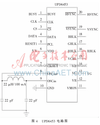
(1) Display control: Determine whether to allow display of characters, flashing frequencies of characters, and control of vibration and start-up of LC oscillation.
(2) Background Control: Determine the type of background (no background, character edge background, character block background, full screen background).
(3) Background color control: determine the color of the background (there are 7 color choices).
(4) Video RAM reset: At this time, the crystal oscillator starts to vibrate, the video RAM write mode, and the color and size of the characters are the default settings.
(5) Display block position control: It is used to determine the distance between the character display block of 12 rows and 24 columns from the uppermost and leftmost ends of the screen.
(6) Display character row and column address control: Determine the position of the row and column in the display block of 12 rows and 24 columns.
(7) Character size, smoothing control: Determine the display size of each line of characters, and whether to use the smoothing of characters when displaying multiple times.
(8) Character RAM write address control: UPD6453 provides 16 characters of RAM space, each character is 12×18 dot matrix. This command is used to determine the dot matrix data to be written to the first few lines of the first word in the RAM space (a total of 18 lines). After writing one line, the row address is automatically incremented by one, and one word is written, and the word address is automatically incremented by one.
(9) Character RAM write data control: Determine the dot matrix data of a row of 12 points that need to be written into the RAM space.
(10) Display character control: Determine which of the 256 characters (including the cured 240 characters and 16 custom characters) of the chip UPD6453 is sent out, and the display color of the character and whether it is blinking.
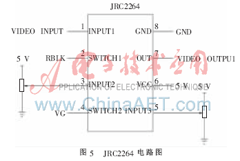
NJC2266 is a high performance video switch with 4.75~13 V voltage; internal 6 dB amplifier circuit; 3 input, 1 output; internal chip clamp function (VIN1), can input video signal; internal brightness signal control function (VIN2, VIN3), used to connect two potentiometer controls to control the brightness of character borders and characters. The specific circuit diagram is shown in Figure 5.
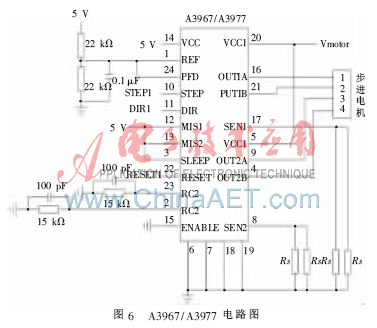
The A3967 uses Allegro 's A3967SLB chip. The chip can drive up to 30 V, ± 750 mA, which is suitable for bipolar stepper motors, and is more convenient than the L297 chip that requires L298 drag. If the load is larger, the 3977 can be used with a drive capacity of 30 V and ±2.5 A. The circuit diagram of A3967/A3977 is shown in Figure 6. The A3967SLB drive stepper motor can achieve up to 8 subdivision drives. This 24-lead SOIC uses the company's EasyStepper interface to reduce eight control lines to two (step and direction), and its embedded converter can be implemented. The control of the stepper motor can be simply input into the pulse of the control motor, without the need for a ring distributor, complicated phase change programming and high frequency control. The A3967SLB's internal circuit protection includes thermal shutdown protection with hysteresis, low voltage lockout and overcurrent protection, and no external power drive. The A3967SLB also features mixed, fast and slow current decay mode selection, built-in PWM current control, synchronous rectification, and low output impedance DMOS power output. The driving method is simple in design, convenient in debugging, reliable in operation, and low in hardware requirements. PWM current control inside the A3967: Each H-bridge has a fixed-cut-time PWM current control circuit that limits the load current to a maximum value. When starting work, a pair of sources on the diagonal accept DMOS in the output state, and current flows through the motor winding and the current sampling resistor connected to the SENCE pin. When the voltage drop across the sense resistor is equal to the D/A output voltage, the current sample comparator resets the PWM latch, thereby turning off the source driver (upper bridge) into slow decay mode; or simultaneously turning off the source accept driver (lower bridge) Enter fast decay mode; or mix mode to generate a loop or current back to the source. This loop (reflow) will continue to decay until the cutoff time, and then the next PWM cycle will be generated. In addition, when wiring the A3967/3977, the ground plane and the wiring of the resistor Rs must be considered.
Constant current high power infrared lamp drive design OCP2030 is a BUCK type DC-DC; with 2% feedback voltage accuracy; wide input voltage, up to 20 V; maximum 3 A current, easy to achieve 5 W LED drive. The SOP8 package; the selection principle of R in Figure 7 is: the requirement is a high power resistor, such as 0.5 W or 1 W, and the package form is 2012 or larger.

If the requirements are not met, multiple low-power LEDs can be used in parallel. In order to meet the black and white conversion of the infrared camera, the 4-pin FB of the OCP2030 can be used to control the operation of the entire chip. The current flowing through the LED is:
I led =0.5 V/R(A)
If R chooses 0.68 Ω, I led =0.7 A
2 The design of the software design software should be based on a modular design, in order to expand the function in the future, and increase the control protocol of the camera. At the same time, the clock frequency of the CPU should be considered. The drive and display of the stepper motor, communication control, etc. need to be processed in time.
This article introduces the scheme and circuit diagram of an infrared camera. On this basis, it can expand its functions and add different modules, such as replacing the MCU to implement a network camera.
references
[1] Zhou Ligong. In-depth explanation of ARM7-LPC213x_214x (on) [M]. Beijing: Beijing Aerospace University Press, 2008, 6.
[2] Guo Xin, Sun Yibo, Gu Hong. Application of UPD6450 and uPD6453 in Video Character Superposition System[J].Application of Electronic Technique,2006,12(3):254-256.
3.2V Battery Cells,Prismatic Phosphate Lithium Batteries,3.2V 202Ah,3.2v lifepo4 battery,3.2V LifePO4 Lithium Battery Pack
Jiangsu Zhitai New Energy Technology Co.,Ltd , https://www.ztbatteries.com
