MAX7219 and MAX7221 LED display drivers for experiments using a computer
The MAX7219 and MAX7221 are 8-digit, 7-segment, common-cathode, mulTIplexed, LED display drivers which drive up to 40mA peak segment current, while operaTIng from a 4V to 5.5V supply. Control is accomplished through a 4-wire ( MAX7219) or SPI (MAX7221) serial interface.
This application note describes a utility program which allows up to 16 MAX7219 or MAX7221 drivers to be controlled from a PC. The utility can be used standalone to help an engineer become familiar with the registers and functions of the drivers or to test an application board prototype by directly controlling the MAX7219 or MAX7221 registers before the equipment's software is designed. RequirementsA PC running Windows 95, 98, 98SE, ME, NT, 2000, or XP with a parallel printer port configured for either LPT1 or LPT2. DescriptionThe utility is a Visual Basic 5 program called MAX7221.EXE which requires the standard Visual Basic run time library MSVBVM50.DLL. The program uses the DriverLINX â„¢ freeware parallel port driver DLPortIO.DLL which provides Win32 DLL hardware I / O functions that are not a standard part of Visual Basic. Windows NT and 2000 users also require the DLPortIO.SYS kernel mode driver. Both of these drivers are copyright Scientific Software Tools, Inc. (). DriverLINX â„¢ is a registered trademark of Scientific Software Tools, Inc. InstallationTo install under Windows 95, 98, 98SE, or ME, download the MAX7219-21.EXE file (800KB). This is a WinZIP self-extracting archive that contains ReadMe.txt, ReadMeSST .txt, MAX7221.EXE, DLPortIO.DLL, and MSVBVM50.DLL. The default download directory is C: \ MAX7221. MSVBVM50.DLL may be deleted if the library is already registered on the computer.
To install on a Windows NT, 2000, or XP platform, download the MAX7219-NT.EXE file (2.3MB). This is a WinZIP self-extracting archive that contains ReadMe.txt, ReadMeSST.txt, MAX7221.EXE, PORT95NT. EXE, and MSVBVM50.DLL. The default download directory is C: \ MAX7221. PORT95NT.EXE is the install program for the DriverLINX drivers which installs and registers the DLPortIO.DLL library and DLPortIO.SYS driver. PORT95NT.EXE can be deleted after installation. Windows 95, 98, 98SE, ME users can also use this installation procedure if they wish.
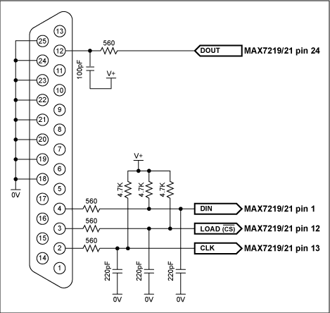
Connecting a MAX7219 or MAX7221 to the Parallel PortThe utility uses 3 of the 8 parallel port printer output lines to drive the LED drivers. A parallel port control input line is used for serial interface read back, and is only needed if registers are to be examined (see the description for the 'Utility' button). You can control up to 16, daisy-chained MAX7221s and / or MAX7219s at once. Either the LPT1 or LPT2 port may be selected from the software. The port can be a standard, ECP, or EPP type. The port connections are shown in Figure 1.

Figure 1. The MAX7219 and MAX7221 connections to the parallel port.
The program brings up 4 windows: main control, intensity control, I / O control, and segment control. The register settings mirror the register power-up conditions of the MAX7219 and MAX7221.
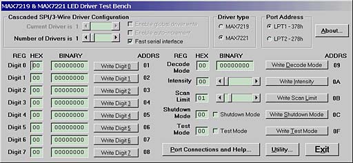
The main control is shown in Figure 2 below. The 'Driver type' radio buttons select whether the software is intended to drive MAX7221s (using a SPI connection) or MAX7219s (using a 4-wire connection).

Figure 2. Program display on startup.
The software controls up to 16 MAX7219 or MAX7221 drivers. The drivers are presumed to be cascaded, (ie, the DOUT pin of the first MAX7219 or MAX7221 connects to the DIN pin of the second MAX7219 or MAX7221, whose DOUT pin connects to the DIN pin of the third MAX7219 or MAX7221, and so on). The total number of MAX7219 or MAX7221 devices is set by the 'Number of Drivers' slider. When this is set to more than 1, the' Enable global driver write 'and' Enable auto-increment 'check boxes are available. When' Enable global driver write 'is clear, only the MAX7221 driver selected by the' Current Driver 'slider is written to when a write command is selected-the others receive the no-op instruction . When 'Enable global driver write' is checked, all the MAX7219 or MAX7221 drivers are written to with the same data. When 'Enable auto-increment' is checked, the current driver number is automatically incremented after each write action. This allows the user to quickly send the same data for a serie s of MAX7219 or MAX7221 drivers.
The serial interface connection to the parallel port can be tested with the 'Test Stream' facility which can be found under 'Port Connections and Help ...' when the program is running. The 'Test Stream' facility transmits the no-op instruction continuously to the MAX7219 (s) or MAX7221 (s) (as set by the 'Number of Drivers' slider) allowing the interface connections to be verified without affecting register contents.
The 'Fast serial interface' check box sets the serial interface speed. When checked, serial interface runs at machine-dependent full speed up to 1 Mbits / sec; unchecked, the speed is limited to 500 bits / sec maximum. The slow speed may be useful when connecting over very long cables. The program will normally only communicate with the target driver (or drivers) when a 'Write' or 'Read' button is pressed.
The 'Utility' button calls up a simple utility which allows the user to send a byte from any register or read a byte from any register. The rules for cascading, auto-incrementing, interface speed etc that have been already set up are followed.
The Exit button, or pressing the Esc key, closes the program. Before closing, the program stores the last settings for device configuration in a file called MAX7221.ini in the same directory that the program was executed from. Nothing is written to the Windows registry. The settings include the position of the main window, and the interface settings on the main window. If the MAX7221.ini doesn't exist then it is created; otherwise it is overwritten. To restore program default settings, or if the MAX7221 .ini is corrupted, simply delete the MAX7221.ini file.
Domestic communication, 4 g module in addition to support two kinds of LTE FDD LTE/TD - LTE standard, also compatible with 2 g / 3 g down, support td-scdma/WCDMA/EDGE/GP/GSM/CDMA1X/EVDO mode. The data service downstream rate can reach up to 100Mbps, the uplink rate can reach up to 50Mbps, providing customers with high-speed Internet access and wireless data connection and other functions. In addition to providing high-speed data access, it also provides voice, SMS, communication book and other functions, which can be widely used in notebook, tablet, touch screen communication devices, smart phones, video surveillance, multimedia mobile phones and vehicle equipment and other terminal products and vertical applications. Today, I will introduce you to what is 4G module and how to use 4G module.
What is 4G module
4G module said TD-LTE and FDD-LTE and other LTE network standards are collectively referred to. It has the characteristics of fast communication speed, wide network spectrum and flexible communication. 4G module refers to a product whose hardware is loaded to the specified frequency band, software supports the standard LTE protocol, and software and hardware are highly integrated and modular. The hardware integrates radio frequency and baseband on a small PCB board to complete wireless receiving, transmitting and baseband signal processing functions. The software supports voice dialing, SMS sending and receiving, dial-up networking and other functions.
Second, how to use 4G module
The 4G module is usually inserted into the circuit board or the patch module is welded to the circuit board, and the corresponding SIM card is inserted, and the network is connected through the 4G cellular network. In the common transparent transmission mode, data can be directly sent to the target server through the 4G module, and the 4G module can receive data from the server at the same time, and send the data to the serial port, which is received by the serial port device connected to the 4G module. Users do not need to pay special attention to the data conversion process between serial port data and network data packets, only need to insert the module to the target position, simple connection and parameter setting, you can achieve transparent transmission between the serial port and the network end.
What is the 4G module How does the 4G module work
4G module, also known as 4G transmission module, 4G communication module, 4G LTE module. It is a kind of hardware loaded to the specified frequency band, the software supports the standard LTE protocol, and the software and hardware are highly integrated modular products, with good compatibility, fast communication speed, large amount of communication data, wide network spectrum, communication flexibility and other characteristics, widely used in electric power, environmental protection, finance, industrial automation and other fields.
The working principle of 4G module
It has the characteristics of fast communication speed, wide network spectrum and flexible communication. The hardware integrates radio frequency and baseband on a small PCB board to complete wireless receiving, transmitting and baseband signal processing functions. The software supports voice dialing, SMS sending and receiving, dial-up networking and other functions.
Through high-speed networking, the 4G module transmits all terminal business data and equipment operating status to the business center in real time. Through the management monitoring platform, the terminal equipment operating status can be monitored in real time and equipment faults can be timely checked. The efficiency has been greatly improved in many aspects such as operating cost, operation scale and service timeliness. Suitable for shared massage chair, public charging pile, vending machine, vehicle system, environmental monitoring, power remote monitoring and other industries.
4G module refers to a product whose hardware is loaded to the specified frequency band, software supports the standard LTE protocol, and software and hardware are highly integrated and modular. It has the characteristics of fast communication speed, wide network spectrum and flexible communication. The hardware integrates radio frequency and baseband on a small PCB board to complete wireless receiving, transmitting and baseband signal processing functions. The software supports voice dialing, SMS sending and receiving, dial-up networking and other functions. Through high-speed networking, the 4G module transmits all terminal business data and equipment operating status to the business center in real time. Through the management monitoring platform, the terminal equipment operating status can be monitored in real time and equipment faults can be timely checked. The efficiency has been greatly improved in many aspects such as operating cost, operation scale and service timeliness.
Good compatibility
4G module supports FDD LTE/TD-LTE two LTE standards, can also be backward compatible with 2G/3G, support LTE-FDD, LET-TDD, WCDMA, TD-SCDMA, CDMA, GSM and other bands.
Large amount of communication data
4G module downstream rate can reach up to 150Mbps, uplink rate can reach up to 50Mbps, to provide customers with high-speed Internet access and wireless data connection and other functions, suitable for large data transmission applications, such as: remote video surveillance.
High communication speed
The 4G module has a lower ping value than the 2G/3G module, and it takes less time for the module to send data packets to receive the response from the server, which is suitable for applications requiring high response speed, such as remote alarm.
4G Module,4G Router Module,4G Wifi Module,4G Lte Wifi Module
Shenzhen MovingComm Technology Co., Ltd. , https://www.movingcommiot.com
