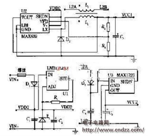
Micropower isolated power supply circuit diagram
Overview:
Regarding the design of the two-wire transmitter micro-power isolation power supply, let us first look at the transmitter? A sensor is a generic term for a device or device that can be measured and converted into a usable output signal according to a certain rule, usually consisting of a sensitive component and a conversion component. When the output of the sensor is a specified standard signal, it is called a transmitter. Common types are power transmitters, current voltage transmitters, and so on.
When developing a low-power intelligent two-wire transmitter, the internal micropower power supply design is critical. First of all, in general, smart transmitters with microprocessors need to meet the power supply of microcontrollers, A/D, D/A and communication circuits. They need more power than ordinary 4~20mA transmitters, and require internal power supply. Has a higher power efficiency. In addition, for capacitive sensors and thermocouples, the grounding or the sensor may be in contact with the casing (grounding). The designed transmitter circuit must be isolated from the input and output to ensure the normal operation of the subsequent control system. And anti-common mode interference capability. Since the external circuit provides a maximum operating current of 4 mA for the two-wire transmitter system, these specific requirements pose great difficulties and challenges for the design of the system power supply. The isolated two-wire transmitter power supply with micro input power is designed with full integrated circuit design, featuring simple structure, stable performance and low cost. It uses 12~35VDC which is dropped on the two-wire transmitter as the input power. It designs a simple constant current regulator front-end input circuit, which consumes 315mA and supplies two sets of isolated 3V power. A set of up to 5 mA load capacity that is not isolated from the input, and a set of maximum 3 mA load capability isolated from the input, fully meeting the power requirements of the input and output isolated two-wire transmitter.
1. Overall design Figure 1 is the power supply schematic. It consists of three main parts: 315mA/812V constant current regulator circuit composed of U1, R1 and Z1; DC/DC conversion circuit composed of U2 as the core; and a set of isolated power supply composed of L2 and U3. The system design strives for streamlining, high integration, and all components have been selected to work in the extended industrial temperature range of -40 to 85 ° C, to ensure reliable power supply for field transmitters.

Figure 1 Power schematic
(Please read the PDF for details)
Shenzhen Esun Herb Co.,Ltd. , https://www.szyoutai-tech.com
