Principle Analysis of Field Oscillation and Field Synchronization Circuit
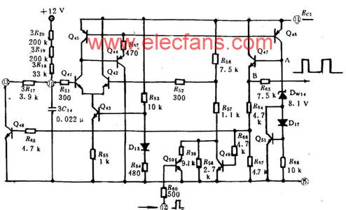
TA7609P midfield oscillation and field synchronization principle 场 The field oscillator in TA7609P is a self-excited multivibrator composed of a positive feedback op amp. As shown in Figure 8 - 36, Q41 and Q42 form a differential amplifier, and form a positive feedback circuit with Q45, Q46, Q47, and Q48. The external capacitor 3C14 is the timing capacitor of the self-excited multivibrator, and Q48 is the discharge tube of 3C14. The external resistor 3R17 is the discharge resistor of the discharge circuit. Q43 is the constant current source of the differential amplifier, Q45 is the collector active load of Q41, and Q45, Q44 and Q46 form the improved constant current source. The collector output signal of Q41 is amplified and shot (Q47), and then Q49 and Q48 are excited by R66 and R65. The collector outputs of Q49 and Q48 return to the bases of Q41 and Q42, and the positive feedback is completed.
Zener diode DW14, diodes D17 and Q51 form a clamp circuit. When Q41 is cut off, Q44~Q49 are all in the off state, the potential at point A is zero level, and the potential at point B is also zero level. At this time, 3C14 is charged by 12V through 3R20, 3R19, 3R18, forming a positive scan. Cheng.
This article refers to the address: http://

Â
When 3C14 is charged to a certain level, UB41>UB42, the differential comparator turns over, Q41 turns on, and Q42 turns off. Since Q41 is turned on, Q44~Q49 are turned on. At this time, 3C14 is rapidly discharged through Q48 to form a scanning reverse stroke. Point A outputs a positive pulse, and point B also outputs a positive pulse whose pulse amplitude is the highest level of point A minus 0.7 V. When Q46 is saturated, the saturation voltage drop is 0.3 V. The breakdown voltage (ie, the stable voltage) of the DW14 is 8.1 V. Considering the forward voltage drop of D17 and the UBE of Q51, the maximum level of point A is about 9.5 V.
The positive field sync pulse is added to the base of Q50 via pin 12 via R60. It is amplified by Q50 and inverted into a negative pulse. It is applied to the base of Q42, and Q42 is saturated and turned on, and forced into the cut-off state in advance. Synchronous operation of the scanning circuit.
When 3C14 discharges to a certain extent, UB42>UB41, the differential comparator will flip again, and Q42 turns on, Q41 turns off, and so on, the field oscillation process is completed. The positive pulse outputted at point B is sent to the sawtooth voltage forming stage to control the charging and discharging process of the integrating capacitor as a switching pulse.
Changing the resistance of the charging resistor 3R20, you can change the charging time constant of 3C14, adjust the forward time, and complete the field frequency adjustment. The resistance of 3R20 increases and the field frequency decreases.
During the scan forward period, Q41 is cut off, and R56, R57, and R58 form a voltage divider circuit, which provides positive bias to Q42 and Q42 turns on. If there is no R58, Q42 is too large, which affects the flip speed of Q41 and Q42. During the scan reversal, R58 is shorted by Q49, Q42 is positively decremented, and Q42 is turned off.
encapsulated power transformer,EI low frequency transformer,Industrial transformer,power supply transformer,alarm system transformer
IHUA INDUSTRIES CO.,LTD. , https://www.ihua-coil.com
