Subvert the imagination! DIY multi-function mobile power supply made by professional engineers
If the ordinary DIY production of mobile power does not require any technical content, then this production, I believe will subvert your opinion, this product has a large battery capacity (up to 30,000mAh), of course, has such a large capacity, must have The corresponding scope of application is reasonable, so the output adjustment, powerful lighting, a variety of indicators, voltage display and other configurations appear on this product, so that it can not only be applied to mobile phones, flat panels, but also can be applied to different environments.
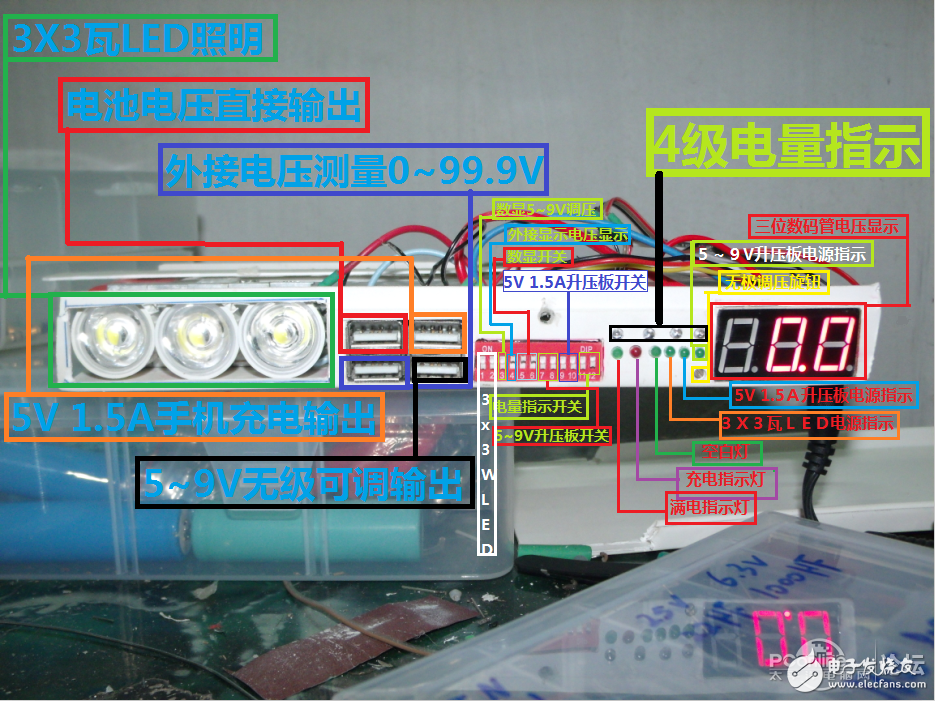
Description of the work: a 30000 mA + 3X3 watt LED lighting + digital display voltage +5 ~ 9V adjustable voltage +5V 1.5A mobile phone charging dedicated output + external voltage display + four-level LED power indicator mobile power.
Three 10000mAh lithium batteries in parallel
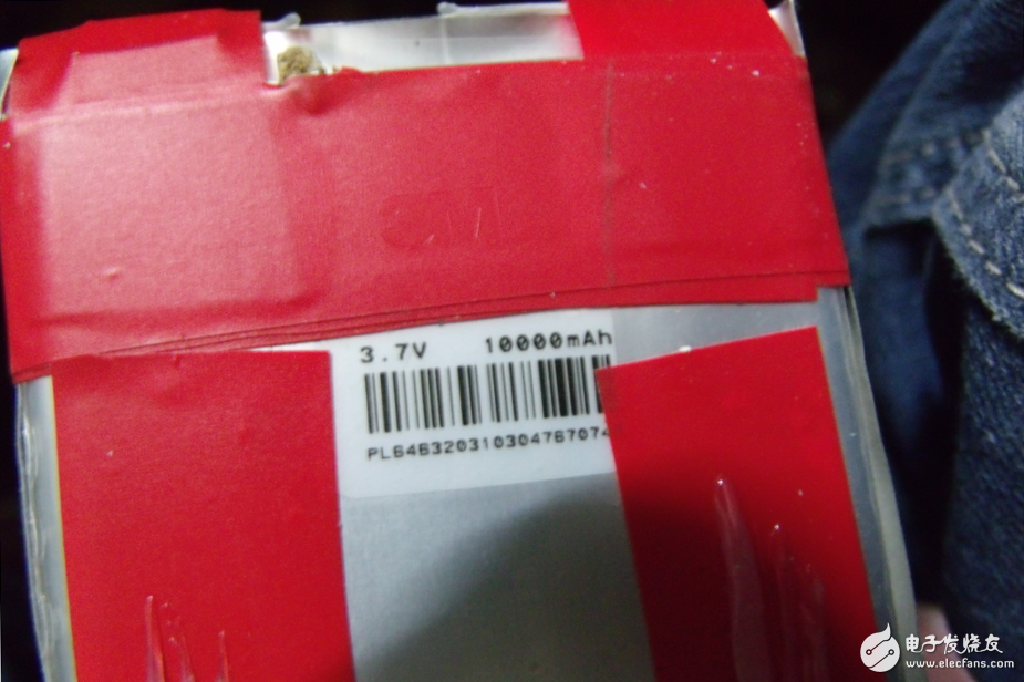
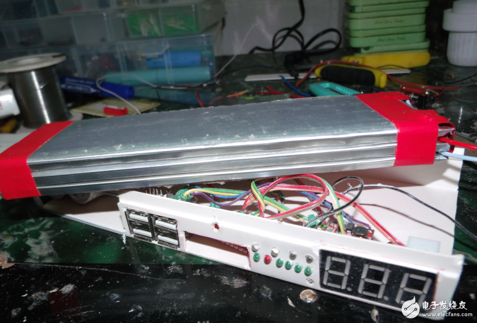
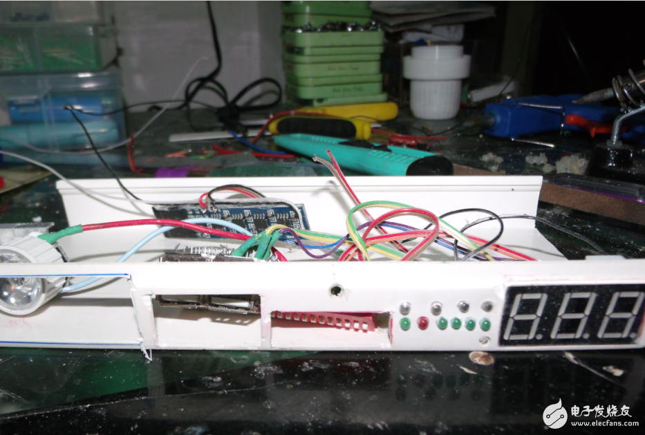
I thought that I used a wooden board to build a box. I thought it would be too much trouble to glue anything, so I went to the hardware store and spent 28 pieces to buy a 10-point line slot to make the box. The location is just right!
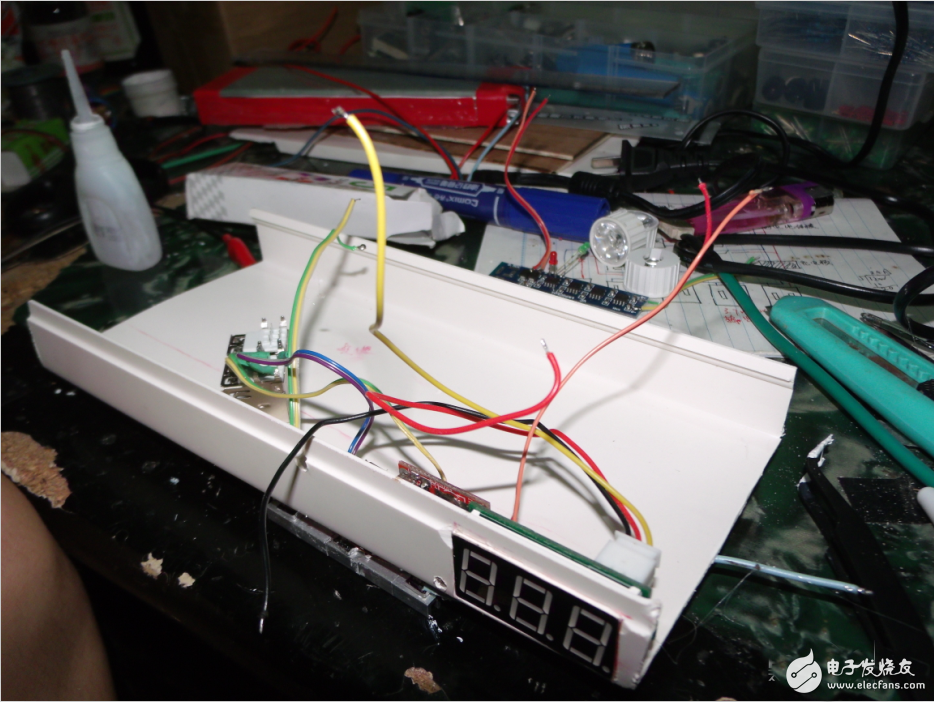
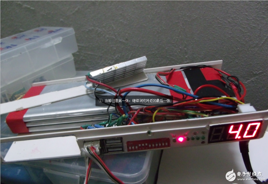
Because there is external voltage measurement and battery voltage direct output function, the two ports can be connected to display the battery voltage. Now it is 4V to see which two USB interfaces are connected by wires?
The picture below shows the voltage regulator display, 5-9V adjustable, but I can adjust it to 4.6.
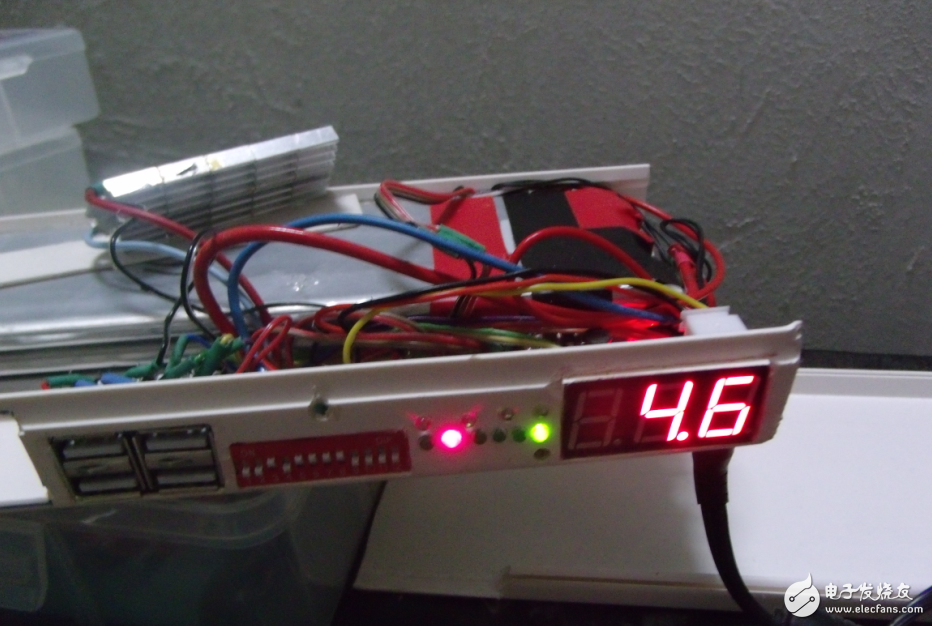
Display voltage with digital tube
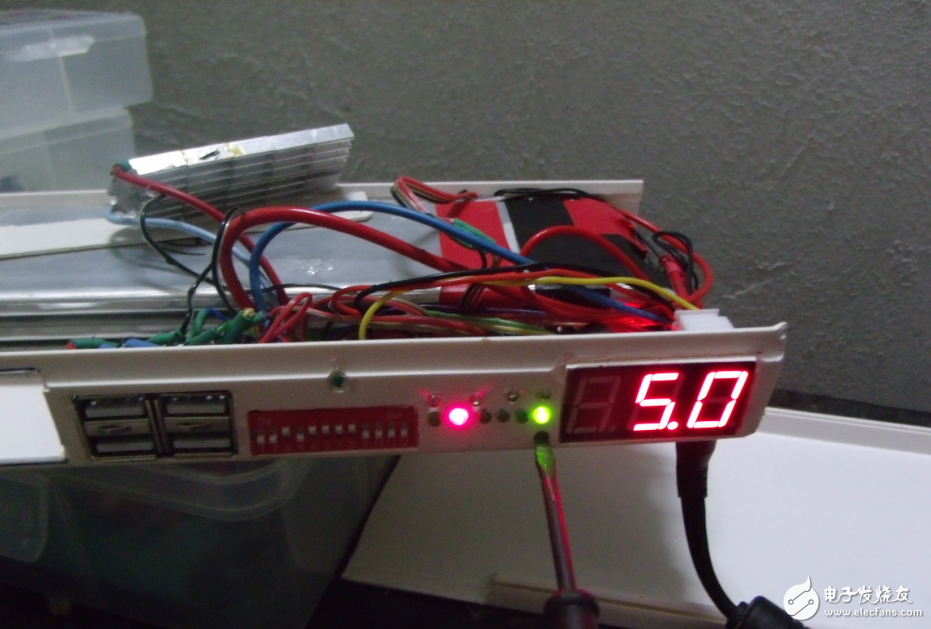
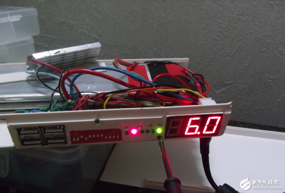
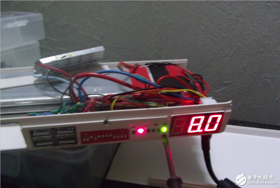
Charge your phone when you switch to 5V!
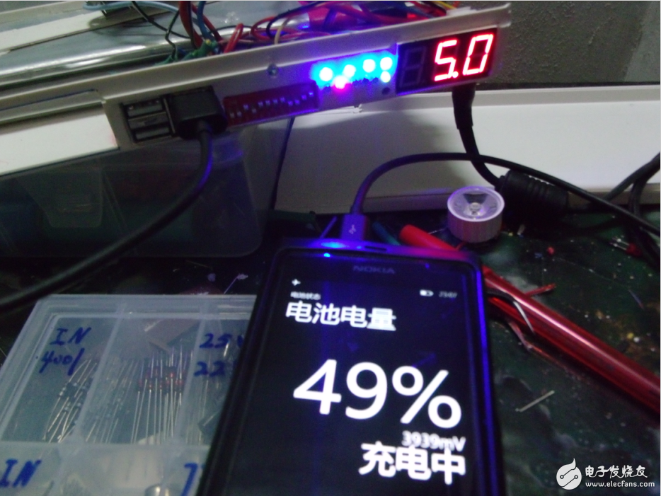
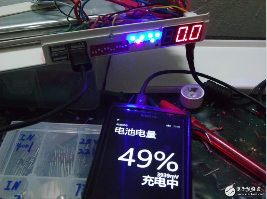
The 5V booster board directly charges the phone!
Finally last function chart:
The following are the remaining DIY mobile power solutions for everyone, which can be used as a reference.
Mobile power (1):
The first is to determine the battery. Most mobile power and notebooks use 18650 batteries. It is a cylindrical lithium battery with a diameter of 18mm and a height of 65mm. Good performance. I bought the best performance on the market, Panasonic made 3100 mAh of this battery
Then there is the Tao board. I found a few pieces, and finally found this baby, the function fully meets my requirements. It can be charged and discharged, and the protection circuit voltage is very stable.
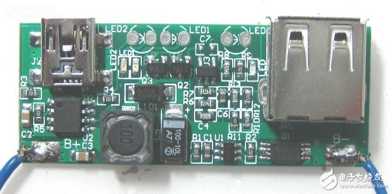
Then design the shell. If you can install the battery, you have to install the circuit board. Still good-looking, the most important thing is that I have to make it by hand, and make a plastic shell directly, if I design it myself. The cost of opening a mold is thousands of tens of thousands, and can't afford it, eventually. I thought of using a plexiglass tube. I used the outer diameter of 25mm and the inner diameter of 21mm. The price is 35 yuan and two meters according to my design. I asked the seller to cut the tube design for 80mm. I won't send it, the structure is quite simple, and I am too lazy to repaint.
After perfecting the design. I decided to rebuild the board for this board. Let it be better combined with the outer casing. I copied the board with protel. Changed to this
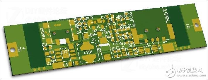
Looking for someone to help me make a finished board
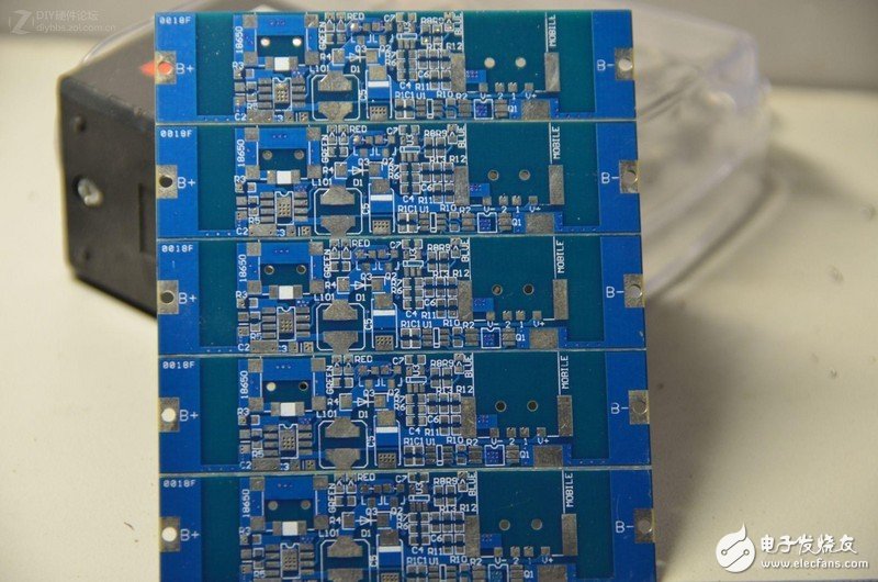
I bought all the components of the same model on the original board on Taobao.
Then I can produce my mobile power.
The first thing to do is to solder the board, the components are small (the smallest component is the 0603 package. That is, the 1.6mmx0.8mm rectangle) is very difficult to solder. If the welding is wrong, it is easy to break the pad, so be careful.
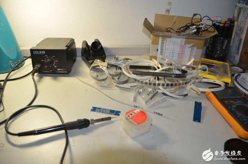
After welding for more than an hour, it was finally completed. Plug in the charging power supply and test it. The three LEDs are on, and it should be successful.
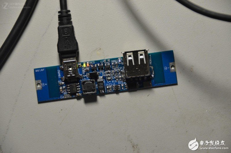
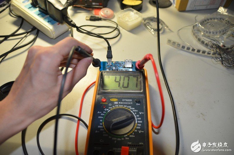
Then measure the voltage, 4.07v. Micro low is normal
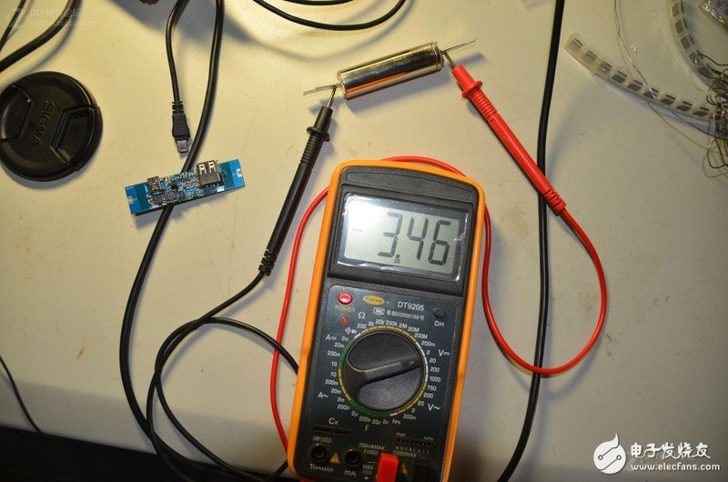
Come check out my battery. I was lighted up by the voltage 3.46v
Try charging. After charging for a while, the voltage has risen to 3.51v. When the charging current is measured, the camera is not taken, and it is not shot.
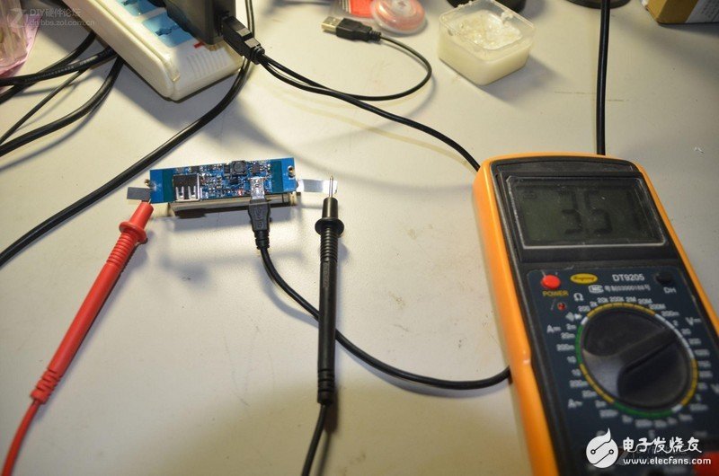
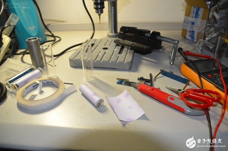
Basically all normal. Let's start the shell, please take out my baby drill, vise and pipe
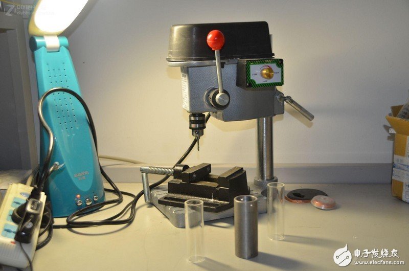
This steel pipe is used as a mold. My sister helped me. Their unit is a train. The round hole above is made by the machine tool of the train. The square trough was made out by me a little bit, and I remember it vaguely. Grinding a day with this unpowered bench drill and several unpowered drill bits.
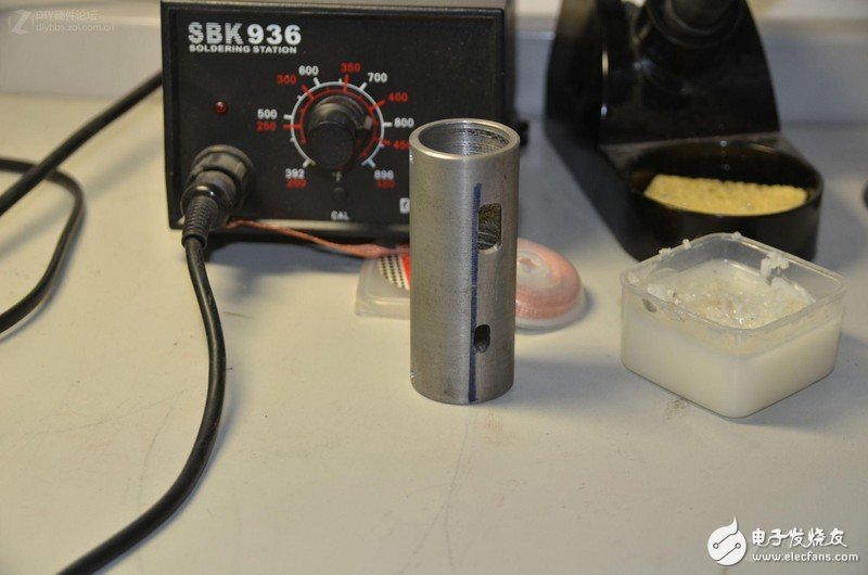
Open drill
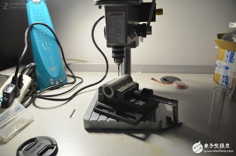
With the mold drill is still very fast, just a few minutes
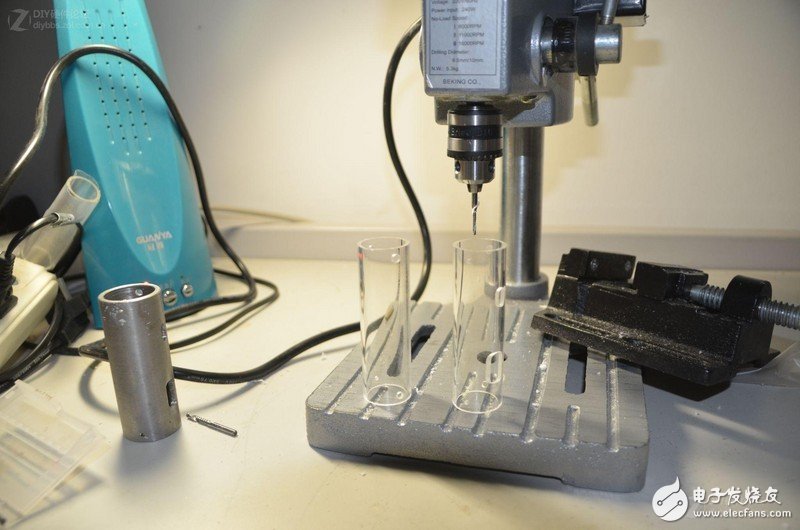
I don't know if you saw the connection between the board and the battery and the appearance of the two tubes when you just tested it. The look of the finished product,
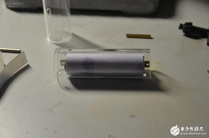
To handle the battery, I cut the nickel sheet above. Nickel tablets are bought when the seller asks me to solder according to my requirements. This welding machine can't be welded by itself. The round hole above is drilled by myself.
See how the visual effect works.
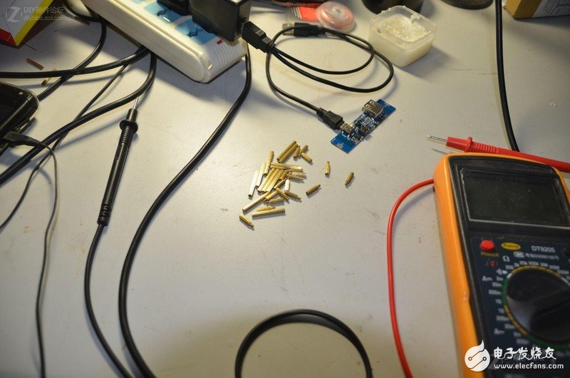
I am using the m2 screw copper column for the connection between the circuit board and the battery. The length is I am good. This type of thing is very comprehensive and can be bought for how long.
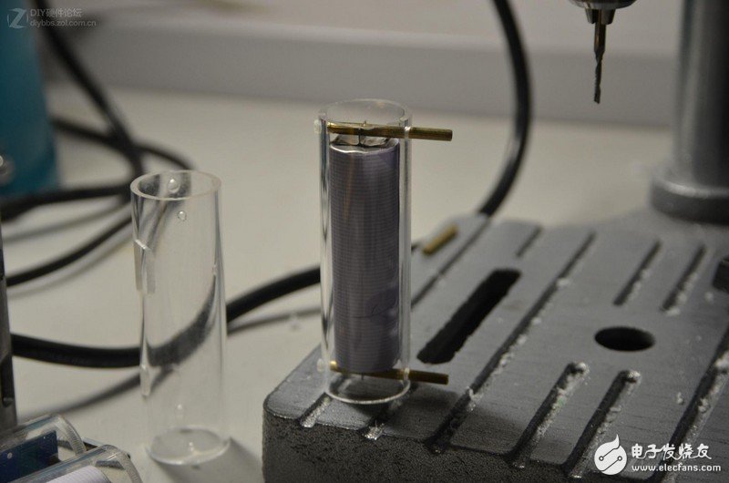
Assemble the connector on the battery end. The screw on the side is non-conductive, if it is iron. The battery is shorted when both ends are in contact with one conductor at the same time. However, in fact, I still like iron, the metal looks good.
Looking for an plexiglass disc for the online shop to cut, I want one yuan,
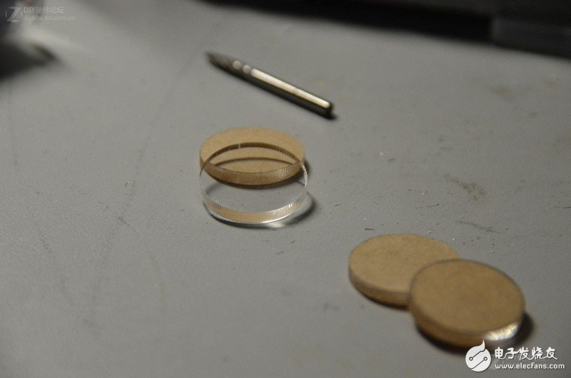
The battery end is generally not a problem. So I chose to glue the seal with glue. A glue with a main component of tetrachloromethane is used. Specially bonded to plexiglass.
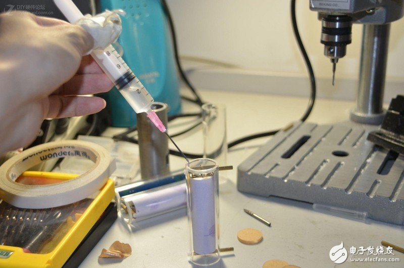
Stick this effect
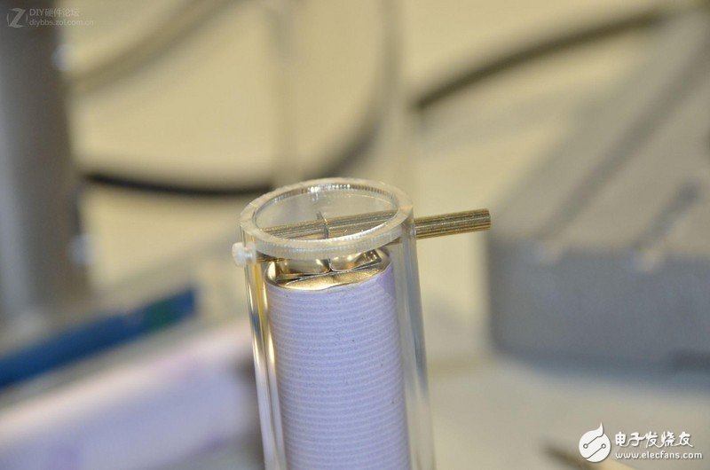
Then connect the board. Charge first, discharge and try to test how stable. Blue light is slightly bright during standby
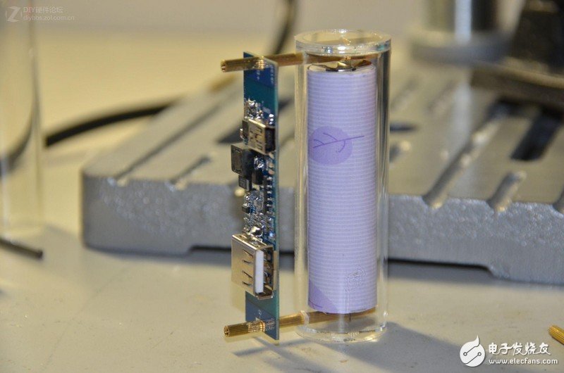
Blue light is strong when discharging
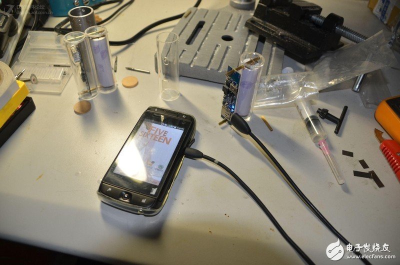
The circuit is charging. Green light is bright blue light
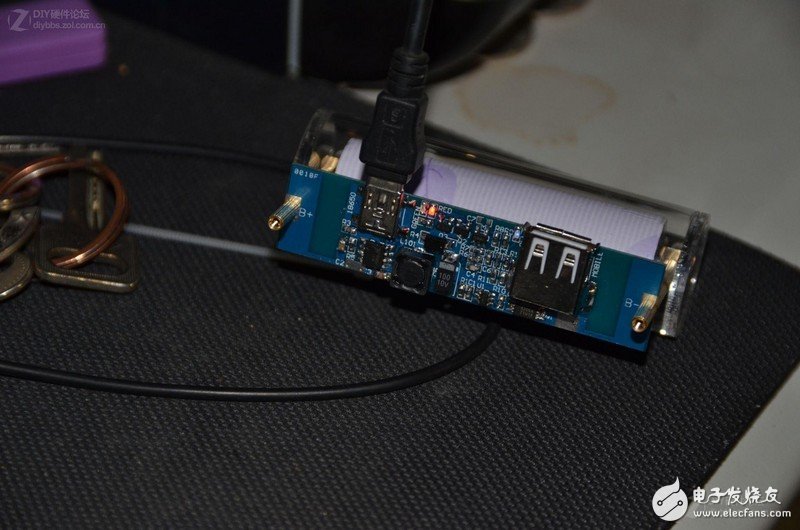
Finally, the remaining half of the outer casing is assembled.
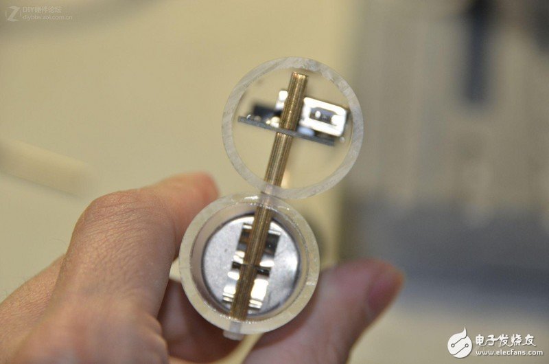
This half may be dismantled in the future. No glue is used. Instead, use a little bit of space. And the elasticity of the material. Tighten the screws a little. Naturally, the wafer is clamped,
Final use rendering
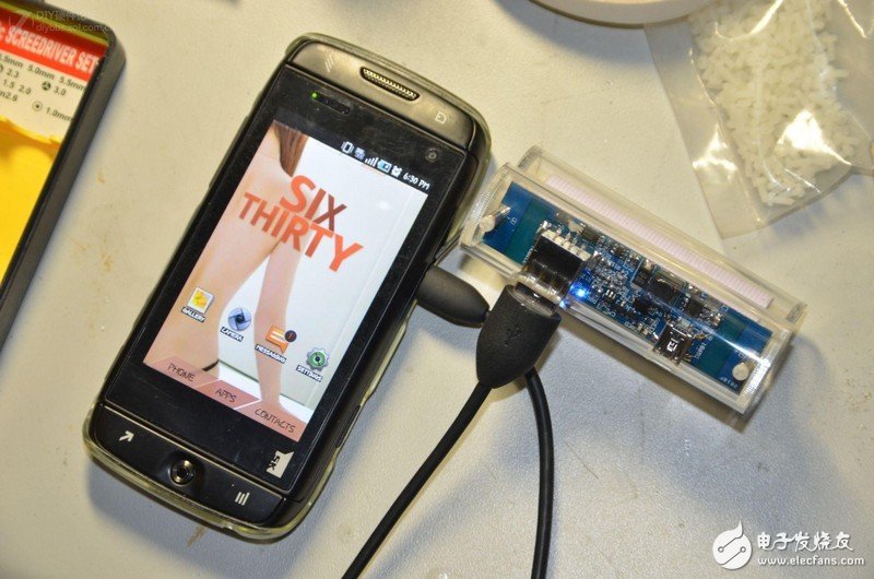
Mobile power (2):
Smartphones are very power hungry, and the phone can't meet the demand once a day. So there is the idea of ​​buying a mobile backup power supply, which was originally intended to be bought online. However, at first glance, which one is expensive~ and both are built-in batteries, and replacing the battery is also a trouble. Well, there are several Huawei 8650 battery charger kits on hand, use this DIY a backup power supply. The webmaster is also a science student. From a young age, he played a kind of gadgets like radio DIY radio. Let's start the DIY mobile phone backup power journey with the stationmaster classmates!
Determine the DIY solution: the battery uses two 1400mah idle mobile phone batteries, and the two chargers are combined to make the outer casing (the latter can be said to be useful, of course, other housings can also be used). Taobao buys a mobile power charging board (about 13 yuan). )
The following is the specification of the charging board I purchased: the first time the charging board is used, it needs a small U port to charge the charger first to activate it.
Specifications: length 50 mm, width 20 mm, height: 9 mm Input: miniUSB input 5V 1A charging is boosted battery voltage range 2.5V-4.2V single-cell lithium voltage (can be used in parallel with multi-cell lithium) Output: Max Support 5V 1.8A output (downward adaptive) Efficiency: The highest efficiency can be up to %86
Boost output voltage: 5V
Note: Because the output has no current limit, everyone is not overloaded.
Charging indication: charging red light is full of green light
Output load indication: blue light is on after the load is turned on (indicating that the board starts working)
Protection function: The protection circuit of the boosted lithium battery has been integrated to prevent over-discharge and overshoot.
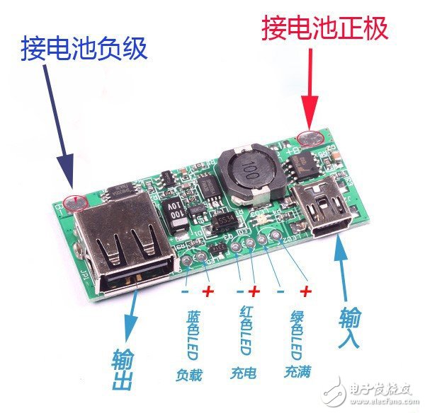
Note: B+ and B- of the boosted battery must not be reversed.
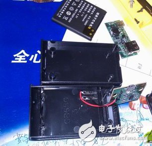
First, this is the mobile phone battery and the matching charger (to be opened)
This is the wiring diagram of the mobile power charging board.
Second, you can start assembling with everything you need:
1. First, remove the charger and remove the circuit board inside. Figure:
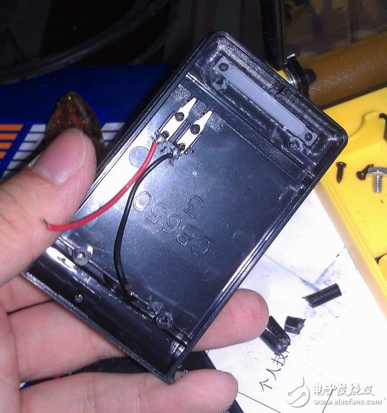
2. Place the charging board back in the charger, the red line is connected to B+, the black line is connected to B-, and the other charger is also disassembled to connect the red line and the black line.
Because the size of the charging board is a little larger, the charger can't be installed. Therefore, it is necessary to make a little modification to the outer casing of the charger, cut the big hole and cut the string.
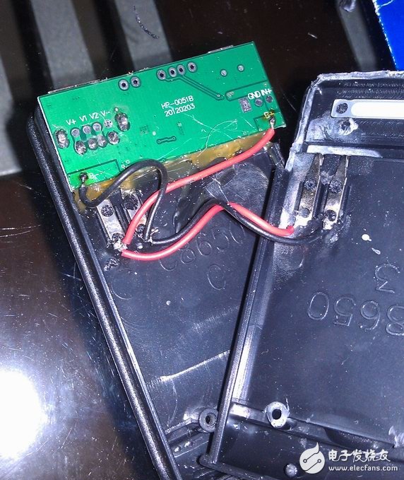
3, the last is to assemble back, simple! The charging board is solidified with silica gel, and the seam of the charger is sealed with silicone.
Install two mobile phone batteries, two parallel is 2800 mAh.
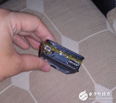
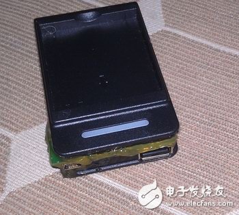
The handwork is a bit poor, and it is also limited to the charger case and the online purchase of the charging pad does not match. However, I only got 13 pieces (excluding postage 10 yuan) and got it.
A 2800mah mobile power supply, what else can I ask for? And the mobile phone battery can be replaced at will, convenient!
4, look at the effect of using it!
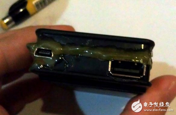
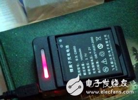
The small U port is used to connect the charger to charge the mobile phone battery on the mobile power source, and the large U port is used for charging the mobile phone.
When connected to the phone, the light is blue. When charging the backup power supply, it is red and the display is green.
Mobile power (3):
I started this DIY trip.
Look at what materials are there:
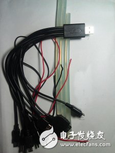
Three Sanyo 14wh capacity polymer lithium batteries (same as millet batteries), 5V3A booster board, 10 in 1 power cord, red and black 60 core wire, hot melt adhesive.
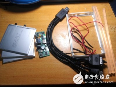
Come to some close-ups:
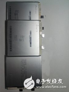
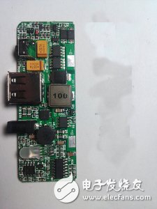
The battery I chose is a 3700 mAh Sanyo polymer lithium battery. This battery will not explode and has high safety. The three pieces are 3700X3=11000mA. The battery voltage is 3.6V, so you need to use the booster board to boost to 5V, and you need to consume a certain amount of power during this conversion process.
The booster board is selected from 5V-3A. The voltage of the general mobile phone charger is 5V-1A, which means that the booster board can charge multiple mobile phones. Tablets such as ipad require 2.1A of current, which means that charging the tablet is more than enough.
Ten-in-one charging line, it is a pity that each type has only one interface. If the two-step interface is the same, only one part of the phone can be charged. 60-core wire, current transmission lever! Hot melt adhesive, fixed booster plate and battery.
OK, the materials are ready and ready to assemble!
1. First, combine the batteries and wrap them together with insulating tape. Use parallel connection to connect them in parallel. The positive and negative poles of the three batteries must be the same.
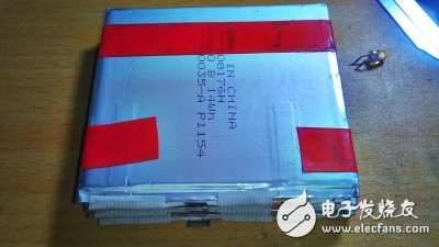
2. Use electric iron and tin wire to solder the red wire of the wire to the positive electrode of the lithium battery. The black wire is welded to the negative electrode and sealed with insulating tape. The length of the red and black wires should be calculated according to the position in advance. I am not enough. Long reconnect (the positive side on the left side is the effect after soldering, the right side is the effect after sealing the tape.) Then continue welding to the booster board (note!! The positive and negative poles must be aligned! Otherwise burned!)
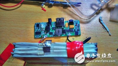
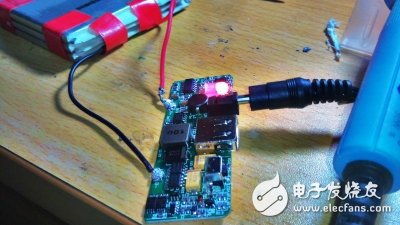
3. Test whether the connection is normal. Plug in the purchased 5V-2A DC interface charger (the booster board INPUT interface is DC). The red light is on, indicating that the connection is normal, otherwise check the line.
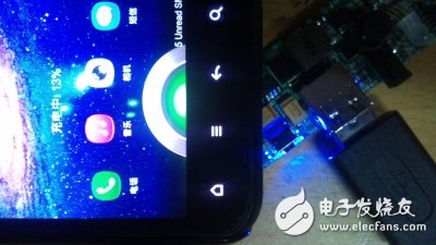
Try to charge your phone
4, the test is no problem, start loading!
Since the purchased mobile hard disk box is not big enough, I have to find it again, just find an iphone4 mobile phone case, transparent plastic case.
According to the position of the board interface, I used the electric iron to burn a few mouths (the hand is poor, everyone will see it)
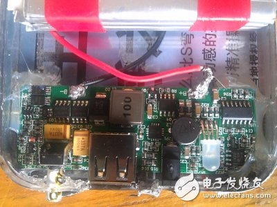
The button is not long enough, use a ballpoint pen to extend it, and stick it with hot melt adhesive. Don't stick the button to it.
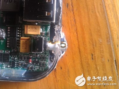
5. After fixing, fix the booster plate and the battery with hot melt adhesive. Be careful not to cover the capacitor and circuit on the circuit board, which is not conducive to heat dissipation and can be applied around. Then wrap the tape around the box and wrap the overall appearance. A mobile power supply is complete! Is not it simple? !
Appreciate the completion map:
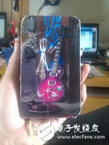
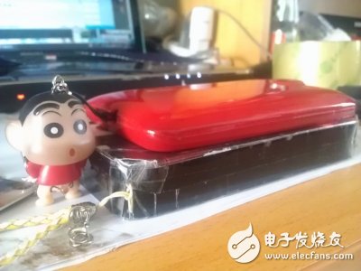
It’s no use to say it well, to test the actual effect.
See how charging efficiency is:
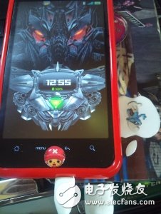
I don't know when it's full, about two hours, and I'll test how many times I can use it later.
According to the calculation:
11000X0.85 charging conversion consumption X0.8 mobile phone conversion consumption = actual capacity 7480 mAh
11000 mAh can charge the following mobile phones:
Iphone 4=5.26 times
MI ONE=3.88 times
DHD=5.98 times
Please convert your own models.
It’s a pity that such a large-capacity mobile power supply only charges one machine.
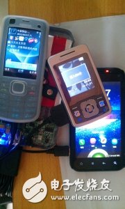
Indicates no pressure
The FirstPower CFPS(2V) and LFPS(6V/12V) series stationary batteries (Opzs Battery) are the newly products which were developed at the end of 2005.
The performances meet the standard DIN40736 and IEC60896-21. tubularPositive plate can prevent the active material from falling off. The grid of positive plate is Pb-Sb multi-alloy
The design life is more than 20 years
Ensuring sufficient electrolyte for battery discharge
Industrial Opzs Battery,Industrial Stationary Opzs Battery,Industrial 2V Opzs Battery
Firstpower Tech. Co., Ltd. , https://www.firstpowersales.com
