The Design of Interference Power Supply Filter Brief Discussion on the Design Process of Interference Power Supply Filter
Everyone should be familiar with the interference power filter, so how much do you know about it? Do you know how the interference power filter is designed? This article mainly introduces the design process of the interference power filter.
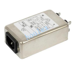
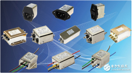
Power filterThe power filter is a filter circuit composed of capacitors, inductors and resistors, also known as "power EMI filter" or "EMI power filter", a passive two-way network, one end of which is the power supply and the other end is the load . The principle of the power filter is one kind-impedance adaptation network: the greater the impedance adaptation between the input and output sides of the power filter and the power and load sides, the more effective the attenuation of electromagnetic interference. The filter can effectively filter out the frequency point of a specific frequency in the power line or the frequency other than the frequency point to obtain a power signal of a specific frequency, or eliminate a power signal of a specific frequency.

The purpose of the power filter is to suppress electromagnetic noise, and the influence of noise can be divided into the following two types:
Emissions: To reduce the noise generated by the equipment that affects the power supply or other equipment below the allowable value of regulations (such as FCC part 15), such as the noise generated by switching power supplies.
Immunity (Immunity): It is to reduce the noise entering the equipment to the extent that it will not cause abnormal actions of the equipment, such as the equipment used in the transmitting equipment of the broadcasting station.
The noise to be suppressed by the power filter can be divided into the following two types:
Common mode: The same noise in two (or more) power lines can be regarded as the noise of the power line to the ground.
Differential mode: The noise between the power line and the power line.
The ability of the same power supply filter to suppress common mode noise and differential mode noise will be different. Generally, it will be explained by the frequency spectrum corresponding to the suppression amount (expressed in decibels).
Interference power filter designThis article takes the design of off-power electromagnetic interference filter as an example to introduce the design process of interference power filter design.
The generation mechanism of switching power supply EM I
The interference generated by the switching power supply can be divided according to the type of noise interference source, which can be divided into spike interference and harmonic interference; if it is divided according to the coupling path, it can be divided into conduction interference and radiated interference. Now explain separately according to the noise interference source:
Insertion loss of EM I filter
Insertion loss is one of the important technical performance parameters of the filter. The central issue considered when designing an EM I filter is to achieve the highest possible insertion loss under the premise of ensuring that the filter meets the requirements of the relevant standards.
EM I filter impedance analysis
The EM I filter is mainly used to suppress electromagnetic interference entering and leaving the equipment, and has two-way suppression.
From the above analysis, it can be seen that in order to make the EM I filter have the best attenuation effect on the EM I signal, the filter impedance should be mismatched with the power supply impedance. The greater the mismatch, the more ideal the attenuation achieved, and the resulting insertion loss The better the characteristics.
According to the above principles, the following principles should be followed when selecting the EM I filter structure:
(1) The series inductance of the EM I filter should be connected to a low-impedance source or a low-impedance load;
(2) The parallel capacitance of the EM I filter should be connected to a high-impedance source or a high-impedance load.
Research on the Network Structure of EM I Filter
The filter is composed of a low-pass filter circuit composed of inductors and capacitors. Since there are two types of interference signals, differential mode and common mode, the filter must attenuate both types of interference. The basic principle is:
(1) Utilize the characteristics of high frequency and low frequency isolation of the capacitor to pass the high-frequency interference current of the positive and negative electrodes of the power supply into the ground (common mode), or introduce the high-frequency interference current of the positive pole of the power supply into the negative pole of the power supply (differential mode);
(2) Utilize the impedance characteristic of the inductance coil to reflect the high-frequency interference current back to the interference source.
The working principle of common mode inductance
As shown in Figure 4, the common-mode inductor is composed of two windings with opposite winding directions and the same number of turns on the same magnetic ring. Usually a toroidal core is used, which has the characteristics of low magnetic leakage and high efficiency. When the current flows through the two windings, it is one entry and the other exit, and the generated magnetic field just cancels out, so that the common mode inductance does not have any obstructive effect on the current. If the common-mode noise current passes through the common-mode inductor, the common-mode noise current is in the same direction. When flowing through the two windings, the magnetic field generated is superimposed in phase, so that the common-mode inductor presents a larger inductance to the interference current. This plays a role in suppressing common mode interference
In actual use, the two inductance windings of the common mode inductor will have an inductance difference due to the winding process, but this difference is just used as a differential mode inductance. Therefore, an independent differential mode inductor is no longer set in the general circuit.
The leakage inductance measurement method of the common mode inductor is shown in Figure 5. Connect one end of the two windings and measure the inductance value from the other end. The measured inductance is the leakage inductance of the common mode inductor.
Selection of common mode inductor materials
When making common mode inductors, which core material should be used, in addition to preventing the core saturation problem, the constant permeability characteristics of the core should also be considered. When the rated current of the inductor is large, whether the inductance is reduced, and to what extent Degree, will it reach saturation.
When winding common-mode inductors, manganese-zinc ferrite, nickel-zinc ferrite, and microcrystalline cores are generally used.
Filter circuit design
The switching power supply parameters used in this example are: Input 24V, output 12V, and power 25W.
This filter circuit adopts the method of adding one stage before and after the power module. The common mode capacitance is 0.01μF, the differential mode capacitance is 6800pF, the common mode inductance is manganese-zinc ferrite, each circuit is wound with 31 turns, and the inductance is 3. 7mH.
Filter result
When the bandwidth of the oscilloscope is 20MHz, the measured ripple before and after filtering are 50mV and 5mV respectively. (The above ripples are all measured under 80% pure resistive load)
Interference power supply filter design process wiring1. There should be no electromagnetic coupling path in the power filter
â‘ The power input line is too long;
â‘¡The input line and output line of the power filter are too close.
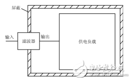
Both of these are incorrect installation methods. The essence of the problem is that there is an obvious electromagnetic coupling path between the filter's input wire and its output wire. In this way, the EMI signal existing at one end of the filter will escape its suppression by the filter, and will be directly coupled to the other end of the filter without being attenuated by the filter. Therefore, the filter input and output must be effectively separated first.
In addition, as the above two types of power filters are installed inside the shield of the device, the EMI signals on the internal circuits and components of the device will be directly coupled to the outside of the device due to the EMI signals generated on the (power) terminal lead of the filter. To make the equipment shielding lose the suppression of EMI radiation generated by internal components and circuits. Of course, if there is an EMI signal on the filter (power supply), it will also be coupled to the internal components and circuits of the device due to radiation, thereby destroying the suppression of EMI signals by the filter and shielding. So it has no effect.

2. The cables cannot be bundled together
Generally speaking, when installing a power filter in an electronic device or system, you should pay attention to that when bundling equipment cables, you must not bundle the wires at the filter (power) end and (load) end together, because this is undoubtedly aggravated The electromagnetic coupling between the input and output ends of the filter severely damages the ability of the filter and equipment shielding to suppress EMI signals.
3. Try to avoid using long grounding wires
The length of the wire connecting the output end of the power filter to the inverter or motor should not exceed 30 cm.
Because a too long ground wire means that the grounding inductance and resistance are greatly increased, it will seriously damage the common-mode rejection of the filter. The better way is to use metal screws and star spring washers to firmly fix the shield of the filter to the enclosure at the power inlet of the device.

The correct installation method of the filter
4. The input line and output line of the power filter must be separated
The input line and output line of the power filter must be separated from each other, avoid paralleling, so as not to reduce the efficiency of the filter.
5. The power supply filter shell and the chassis shell must be in good contact
The metal shell of the special filter for the inverter must be in good surface contact with the chassis shell, and the grounding wire must be connected well.
6. The connecting wire of the power filter should be twisted pair
It is better to use shielded twisted-pair cables for the input and output connection lines of the power filter, which can effectively eliminate some high-frequency interference signals.
ConclusionFor the design of interference power filter, this article firstly describes the generation of switching power supply EM I, and then focuses on the analysis of the design principle of EM I filter, especially the common mode inductor that plays a very important role in it. Finally, under the guidance of the above-mentioned theory, an EM filter circuit for a certain type of switching power supply was designed, and good results were achieved. So far, the introduction of the interference power filter design is over, and I hope this article can help you.
Teaching Ferrite Magnet,Magnet Disc,Hard Ferrite Magnet,Water Pump Rotor Magnet
HU NAN YUBANG MAGNETIC MATERIAL CO.,LTD , https://www.ybmagnet.com
