Where can the agc circuit be applied (radar, receiver)
This paper first introduces the application and classification of AGC circuit, secondly describes the application of agc circuit in radar, and finally introduces the application of agc circuit in receivers.
Application of AGC CircuitThe common requirements of modern receivers can be summarized as wideband, high sensitivity, large dynamics, and high stability. No matter what kind of system receiver, it has high dynamic range requirements. The functional circuit that realizes the dynamic range of the receiver is AGC in the receiver, AGC circuit is mainly made up of control circuit and controlled circuit two parts. The control circuit is the generating part of the ACC DC voltage. The function of the controlled circuit is to change the gain of the receiver according to the changed control voltage generated by the control circuit. The total gain of the receiver is usually distributed at all levels of the AGC circuit. The cascade of AGC circuits at all levels constitute the total gain.
Classification of AGC CircuitsThe AGC circuit can be divided into an analog type that is accomplished with an electronically controlled attenuator and other analog circuits, and a digital type that uses a digitally controlled attenuator to accomplish the gain control of the circuit. Several AGC circuits will be highlighted here: the peak AGC circuit, the gating AGC, the time-gain control (STC), and the digital ACC. The first three are analog AGCs and the last one is the digital AGC.
Analog type AGC peak type AGC circuit: The peak detector is used to separate the horizontal synchronization signal from the video signal, and then it is smooth filtered by an external capacitor, and becomes a DC voltage that reflects the strength of the signal, which is amplified by the video amplifier. The voltage to control the attenuator. Gated AGC: When there are multiple targets in the tracking area, the receiver will receive thousands of echo signals, however the tracking device can only track a single target. If the tracked target signal is weak, the receiver must have higher gain. Therefore, the best way is to use the gating circuit to select the desired echo signal. After the threshold setting, peak protection, and amplification, the AGC control voltage is output. Sensitivity time control (STC): When the tracking device performs a wide range of target searches, it is often necessary to open the distance strobe wave to a wide range. In this case, an STC circuit is needed.
The specific method is to set the attenuation amount to a large initial value after the strobe triggering, so that the short-range clutter interference is suppressed. Because the short-range noise is relatively high, this gain is still sufficient to find the target. As the distance increases, the attenuation of the receiver gradually decreases, which in turn ensures the discovery of long-range targets. Digital AGC: Use a digitally controlled attenuator to adjust the mid-range gain by controlling its amount of attenuation. There are two ways to implement it. One is to implement a closed loop by the receiver itself, to amplify the signal after detection, to hold the A/D sample, to send the digital attenuator as control data, and to control the digital attenuator with data. To achieve the purpose of control gain; the second by the signal processor to send AGC control signal, CNC attenuator control by the signal processor to complete the receiver system closed loop.
Considering the advantages and disadvantages of several AGC circuits in a comprehensive manner, although the peak AGC circuit has poor temperature performance in early receivers, the temperature is easy to change, and the control curve is prone to drift, the circuit is simple and closed-loop AGC without external signals. In conjunction with the use, such as digital AGC, the second method requires the signal processor to send the AGC control signal. In recent years, with the rapid development of technology and process means, a large number of logarithmic detectors with high accuracy and temperature stability have emerged, and a variable gain amplifier VGA has emerged, and the factors that restrict the temperature performance of the AGC have been solved, making the method Circuits are widely used.

1, peak type AGC
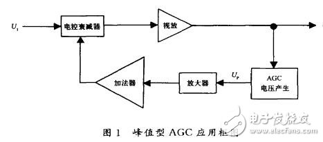
Using the detected DC voltage as the AGC control voltage, the specific application block diagram is shown in Figure 1.
The AGC voltage generation circuit is completed by the circuit shown in FIG.
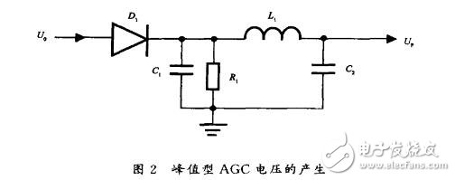
In an altimetry radar, U. For a 50ns pulse signal, the repetition period T = 1 ms, because the pulse width is too narrow, the pulse period is low, and the discharge time constant t=R1XC1=200kQX0.01Up=2ms is selected according to the needs of the actual electric control attenuator, t is greater than the repetition period T, so when the next pulse signal arrives, Cl is recharged, so that repeated charge, discharge, in Cl, RI to get an approximate DC voltage. Then give Ur after smoothing by low-pass filtering of l.1 and C2.
The amplifier uses the low-drift operational amplifier AD707. The Ur signal is converted by the adder to control the curve so that it can reach the voltage required for AGC control. The test results of the output voltage (V) and attenuator control voltage (V.) are shown in Table 1.

The range of AGC control can reach 70dB, completing the role of the receiver self-closed loop. This scheme is used because it is applied to the altimetry radar of an aircraft. The target is the earth. It is hoped that the entire radar system will be simple and lightweight, and the receiver will close its own loop.
2. Gated AGC
The gated type AGC is applied to a single target tracking radar receiver developed by us, and it has stronger anti-interference ability. The echo signal reflected from the target is used to control the tracking system so that the radar antenna tracks the target and moves as the target moves. Its block diagram is shown in Figure 3.

When there are several targets in the airspace pointed by the radar antenna at the same time, the receiver will receive more than one echo signal. Since the tracking radar only tracks a single target, the radar antenna will be at a loss. The solution to this problem is to select the target echo signal to be tracked by the radar operator to adjust the "gated wave gate" and send it to the tracking agency after peak protection and amplification.
From the perspective of the operation of the AGC circuit, it is not suitable to use all the echoes to generate the AGC control voltage. If the tracked target signal is weak, the receiver must have higher gain. Therefore, the best way is to use the gating circuit to select the desired echo signal. After the threshold setting, peak protection, and amplification, the AGC control voltage is output.
Second, the application of agc circuit in the receiverWhen the receiver receives a signal, the input signal level varies widely (below -100 dBm or less, up to 15 dBm or more) due to variations in the ionosphere, fading, and conditions of the received signal. The output power of the machine varies with the size of the external signal, so the output of the receiver will have very different signal power. If you want to keep the linear amplification of receivers and signal unsaturation distortion in such a wide range, you need to control the gain of the receiver so that the output signal maintains an appropriate level to ensure the normal operation of the receiver. Therefore, automatic gain control is highly emphasized in the receiver. At present, there are mainly two methods for controlling the gain of the amplifier in the short-wave receiver: one is to change the parameters of the amplifier itself, and the gain is changed. Typically, a double-gate FET is used to change the DC offset of one of the gates. The voltage is set to vary the gain; the other is to insert a variable attenuator between the amplifier stages to control the amount of attenuation and change the gain. Typical are various integrated variable gain amplifiers.
The following mainly uses the AD8367 as a variable gain amplifier and uses the AD8361 as an external detector to control the AD8367. With the AD820 differential amplifier and other analog circuit designs, an AGC circuit with a dynamic range of 80 dB is completed. At the same time, the circuit principle, circuit layout of the chip layout, gain control and voltage relationship are explained in detail, and the AGC start control mode, working conditions and experimental results are specified.
Peak type AGC circuit design
The AD8367 is a variable gain single-ended F amplifier with excellent gain control. Since the root detector is integrated on the chip, it is also a VGA chip that can implement a single-chip closed-loop AGC. The chip features a high performance 45dB variable gain amplifier that controls linear gain and can operate stably at any frequency from low frequencies to 500 MHz. When the input terminal is at zero level, the output level is half of the power supply voltage and it is adjustable.
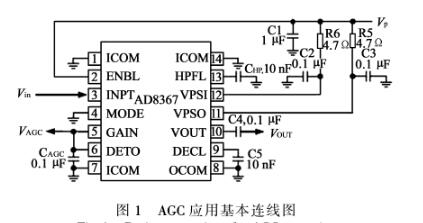
The AD8367 operates from +5 V and is available in two operating modes: GAIN UP and GAIN DOWN modes. In the former mode, it can be used as an ordinary voltage-controlled gain amplifier. In the latter mode, it can easily implement the function of an AGC circuit. Figure 1 shows the basic connection diagram of a monolithic AGC amplifier configured using the internal integrated accurate root-root detector.
In an AGC loop, the greater the gain of the loop, the better. The AD8367 is used as the AGC loop's controllable gain amplifier. Its 3 dB gain cutoff frequency reaches 500 MHz. With a center frequency of 70 MHz, the maximum gain is +42.5 dB, the minimum gain is -3.7 dB, and the gain control factor is 19.9 mV/dB, specific features shown in Figure 2
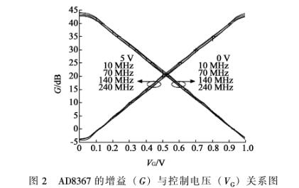
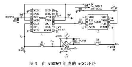
Figure 3 shows the implementation of the AD8367-based AGC loop. Since the AD8367 internal AGC control output level is +4 dBm, it is limited in some cases, which requires the use of external detectors to adjust
AD8367 control point. The AD8367 uses an external detector, the AD8361, for detection. The output voltage, VAAGC, is applied to the AD820 differential amplifier to generate V after voltage division. To control the AD8367. The difference amplifier threshold level Vser is set to 1 V, and the detection voltage is differentially amplified.
Android Tablet PC has a wide range of applications, applicable to airports, railway stations, municipal buildings, large shopping centers, department stores, banks, hotels, stock exchanges, gymnasiums, large shopping centers, advertising display, monitoring, corporate departments and entertainment places - trade exhibition, business conference center, concert hall, Land Bureau, real Estate Trading Center, cinema retail stores , restaurants, exhibition halls, pop music billboards, cosmetics display window signs, car sales display signs, etc.
android tablet pc,best android tablet,android tablet 4K,android industrial tablet,tablet pc android,android tablet computers
Shenzhen Hengstar Technology Co., Ltd. , https://www.angeltondal.com
