Analysis of LED Driver Circuit Design Method
LED has many advantages such as environmental protection, long life and high photoelectric efficiency. In recent years, its application in various industries has been rapidly developed. The LED drive circuit has become a key factor in product application. In theory, the service life of LEDs is more than 100,000 hours. However, in the actual application process, LEDs are easily damaged due to improper selection of drive circuit design and driving methods.
When designing the LED driver circuit, it is necessary to know the LED current and voltage characteristics. Due to the different LED manufacturers and LED specifications, the current and voltage characteristics are different. Taking the typical specification of white LED as an example, according to the current and voltage variation rules of LED, the general application forward voltage is about 3.0-3.6V, the typical value is 3.3V, the current is 20mA, and the forward voltage of the LED exceeds 3.6. After V, the forward voltage has only a small increase, but its forward current may increase exponentially, causing the temperature of the LED illuminator to rise too fast, thereby accelerating the LED light attenuation, shortening the life of the LED, and even burning when severe. Bad LED. According to the voltage and current variation characteristics of the LED, strict requirements are imposed on the design of the driving circuit.
At present, many manufacturers produce LED light products (such as guardrails, lamp cups, and projection lamps), which use a RC capacitor, and then add a Zener diode to supply power to the LED. This way, the LED is simple and cheap, but there is a pole. Large defects, first of all, are inefficient, consume a lot of power on the buck resistor, and may even exceed the power consumed by the LED, and cannot provide a large current drive, because the larger the current, the larger the buck capacitor is required, so the consumption is lower. The greater the electrical energy on the voltage resistor. Secondly, the ability to stabilize the voltage is extremely poor, and it cannot be guaranteed that the LED current does not exceed its normal working requirements. When designing the product, the voltage across the LED is used to drive the power supply, which is at the cost of reducing the brightness of the LED. When the LED is driven by the RC mode, the brightness of the LED cannot be stabilized. When the voltage of the power supply is reduced, the brightness of the LED becomes dark. When the voltage of the power supply increases, the brightness of the LED becomes brighter.
According to the LED current and voltage variation characteristics, it is feasible to drive the LED with constant voltage. Although the commonly used voltage regulator circuit has the disadvantages of insufficient voltage regulation accuracy and poor current flow capability, it may be designed accurately in some products. The advantage is still that other driving methods cannot be replaced.
The constant current driving method is an ideal LED driving method, which can avoid the current fluctuation caused by the change of the LED forward voltage, and the constant current stabilizes the brightness of the LED. Therefore, many manufacturers choose constant current to drive LEDs. There is also a kind of LED driving method that is feasible. It does not have constant voltage or constant current. However, through the design of the circuit, when the forward voltage of the LED rises, the driving current is reduced, which ensures the safety of the LED product . Of course, the rise of the forward voltage can only be in the range of the LED, and too high will damage the LED.
The ideal LED driving method is to use a constant voltage, constant current, and cascade multiple LEDs in series. But the cost of the drive increases. In fact, each type of driving method has advantages and disadvantages. According to the requirements and application of LED products, the LED driving method is reasonably selected, and the precise design of the driving power supply becomes the key.
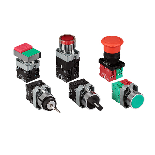
XB2-B Series Pushbutton Switch
XB2-B series Pushbutton Switch are using controlling circuit of AC voltage up to 660V/AC 50Hz.and DC voltage below 400V.It is used for controlling signal and interlocking purposes.The main body of the push buttons adopts Circuit head,with chromium plated metal bezel,Complete units with screw and captive cable clamp connections.The contact adopts special silver alloy in order to enjoy the benefit of high anti-electrical erosion.The signal lamp series are suitable for electrical applicances circuit of AC voltage up to 380V/50Hz,and DC voltage below 380V.It is ideal for using as indicating signals,warning signals,emergency signals.

Push Button On Off Switch,Waterproof Push Button Switch,Micro Push Button On Off Switch,Green Push Button Switch
Ningbo Bond Industrial Electric Co., Ltd. , https://www.bondelectro.com
