Several common control circuit schematics
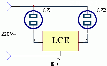
Schematic diagram of the synchronous control socket circuit of the cooling fan The working principle of the application circuit of the device is shown in the following figure. For heat dissipation from electrical equipment, a cooling fan can usually be used to dissipate heat. The synchronous control socket made of LCE does not need to make any changes to the device and its line. Just plug the power plug of the power device into the power socket CZ1 and plug the plug of the electric fan into the power socket CZ2. When the electrical equipment is powered on, the electric fan will automatically start running, and when the power of the electrical equipment is disconnected, the electric fan will stop working.
This article refers to the address: http://
Electric meter empty load energy saver circuit schematic
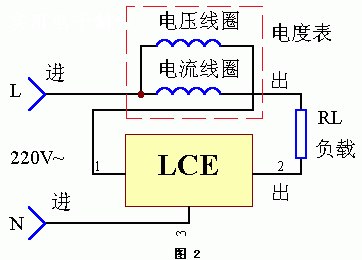
The application circuit of the device works as shown in the figure below. We know that in the watt-hour meter, the voltage coil and the current coil are connected in parallel to the grid, and the voltage coil is always consuming power regardless of whether a load is connected to the loop. If we use the LCE module, we can completely solve the problem of air consumption of the meter. When the load RL is connected in the current coil circuit, the voltage coil is also turned on immediately, which does not affect the electricity metering; when the load RL is disconnected, the voltage The current in the coil is also cut off, so there is no-load loss.
Common antenna amplifier power supply controller circuit principle
The application circuit of the device works as shown in Figure 3. Usually the power amplifiers that share the antenna amplifier and the user's TV are separate. Sometimes no one can work on the TV, and the antenna amplifier is still powered on, consuming power in vain. At other times, there may be multiple TV sets receiving the program, and the power switch of the shared antenna amplifier is not closed, which of course does not get good reception. Automatic control is easy with the LCE module.
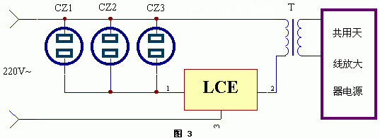
When the TV set sockets CZ1, CZ2, CZ3 (of course, it is also possible to design and install more power sockets, as long as the LCE power used allows), the power switch of the TV is turned on, and the antenna amplifier is shared. The power is automatically supplied. This will not waste energy, and will not affect the TV users, and does not require special management.
High and low voltage sequence control switch working principle
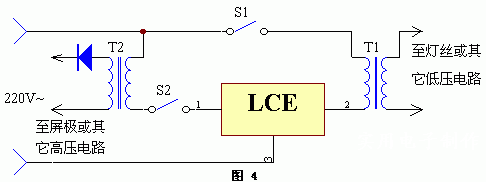
The application circuit of the device works as shown in the figure below. In some electronic equipment consisting of vacuum tubes or some other equipment, several power supply voltages, such as high voltage and low voltage, need to be started in a certain order. If you are negligent, you may be mistaken. The use of the LCE module can solve this problem. T1 is a low voltage transformer whose primary winding is connected in series in pin 2 of the LCE; T2 is a high voltage transformer whose primary winding is connected in series in pin 1 of the LCE. The order of normal start-up should be: first press switch S1, after a while, let the filament of the vacuum tube preheat, then press switch S2. If the order of operation is reversed, the switch S2 is first pressed and its circuit will not work, thus ensuring the correctness of the operating procedure.
Projection room light synchronous converter works
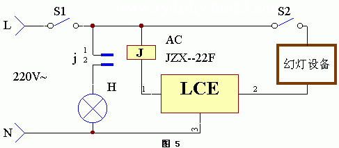
The application circuit of the device works as shown in the figure below. When lighting a slide show, a movie, or a video, it is often necessary to turn off the indoor lighting. At the end of the show, the lights will be illuminated immediately, and this automatic conversion may be easily accomplished using the LCE module.
When the projection power switch S2 is closed, the AC relay J is immediately energized, its normally closed contact j is turned off, the power of the illumination lamp H is turned off, and H is turned off. At the end of the show, the switch S2 is turned off, at which time the relay J is released, its contact j is reset and closed, and the illumination lamp H is electrically lit. S1 is an indoor power switch.
Power failure emergency light automatic converter works
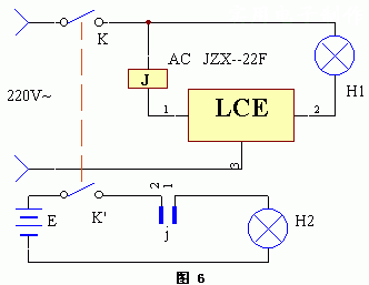
The application circuit of the device works as shown in the figure below. In special occasions where the lighting is not allowed to be interrupted (such as surgery, etc.), the power failure emergency light automatic converter made by the LCE module can achieve the uninterrupted illumination after the power failure. Among them, H1 is a normal lighting device; H2 is a lighting device in case of power failure emergency.
Zysen offer Straight Waveguide, from WR6 to WR975, length is customized according to requirement, Quick lead time 2 to 3 weeks.
H Bend Waveguide,Straight Waveguide,Waveguide Pressure Window,Microwave Straight Waveguide
Chengdu Zysen Technology Co., Ltd. , https://www.zysenmw.com
