Audio amplifier design technology TPA31xxD2 main features
TI's TPA31xxD2 series is a stereo high-efficiency digital power amplifier capable of driving 2 ohm speakers up to 100W. Operating voltage 4.5 V – 26 V, efficiency greater than 90%. TPA3130D2's high efficiency can be achieved with a single layer PCB, without the heat sink providing 2x15W output power TPA3118D2 uses double-layer PCB, no heat sink provides 2x30W/8 ohm output power, TPA3116D2 uses small heatsink to provide 2x50W/4Ω output power, mainly used for small/micro component strip speakers, aftermarket automotive electronics, CRT TV And consumer audio. This article describes the main features of TPA31xxD2, block diagram, application circuit diagram and evaluation board TPA3116D2EVM main indicators, circuit diagram, bill of materials and PCB layout.
The TPA3xxD2 series are stereo efficient, digital amplifier power stage for driving speakers up to 100W/2Ω in mono. The high efficiency of the TPA3130D2 allows it to do 2x15W without external heat sink on a single layer PCB. The TPA3118D2 can even run 2x30W/ 8Ω without heat sink on a dual layer PCB. If even higher power is needed the TPA3116D2 does 2x50W/4Ω with a small heat-sink attached to its top side PowerPad. All three devices share the same footprint enabling a single PCB to be used across Different power levels.
The TPA31xxD2 advanced oscillator/PLL circuit employs a mulTIple switching frequency opTIon to avoid AM interferences; this is achieved together with an opTIon of Master/Slave option, making it possible to synchronize multiple devices.
The TPA31xxD2 devices are fully protected against faults with short-circuit protection and thermal protection as well as over-voltage, under-voltage and DC protection. Faults are reported back to the processor to prevent devices from being damaged during overload conditions.
Main features of TPA31xxD2:
Supports Multiple Output Configurations
2×50-W into a 4-Ω BTL Load at 21 V (TPA3116D2)
2×30-W into a 8-Ω BTL Load at 24 V (TPA3118D2)
2×15-W into a 8-Ω BTL Load at 15 V (TPA3130D2)
Wide Voltage Range: 4.5 V – 26 V
Efficient Class-D Operation
90% Power Efficiency Combined with Low Idle Loss
Greatly Reduces Heat Sink Size
Advanced Modulation Schemes
Multiple Switching Frequencies
AM Avoidance
Master/Slave Synchronization
Up to 1.2 MHz Switching Frequency
Feedback Power Stage Architecture with High PSRR Reduces PSU Requirements
Programmable Power Limit
Differential/Single-Ended Inputs
Stereo and Mono Mode with Single Filter Mono Configuration
Single Power Supply Reduces Component Count
Integrated Self-Protection Circuits Including
Over-Voltage, Under-Voltage, Over-Temperature, DC-Detect, and
Short Circuit with Error Reporting
Thermally Enhanced Packages
DAD (32-pin HTSSOP Pad-up)
DAP (32-pin HTSSOP Pad-down)
–40°C to 85°C Ambient Temperature Range
TPA31xxD2 application:
Mini-Micro Component, Speaker Bar, Docks
After-Market Automotive
CRT TV
Consumer Audio Applications
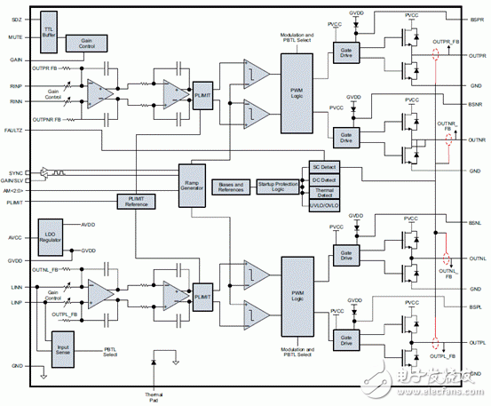
Figure 1. Block diagram of the TPA31xxD2 series
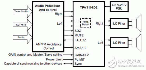
Figure 2. SPA31xxD2 Series Simplified Application Circuit Diagram
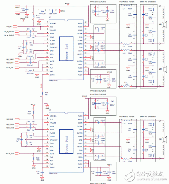
Figure 3. TPA31xxD2 Series Application Circuit Diagram
Evaluation Board TPA3116D2EVM
The TPA3116D2EVM evaluation module (EVM) demonstrates the integrated circuits TPA3116D2 from Texas Instruments (TI).
The TPA3116D2 is a 50-W (per channel), efficient, stereo, digital-amplifier power stage for driving two bridge-tied speakers or a single parallel bridge-tied load. The TPA3116D2 can drive a speaker with an impedance as low as 3.2 Ω (4 Ω typical).
The TPA3116D2 is available in a 32-pin TSSOP.
The TPA3116D2 evaluation module consists of a single 50-W, Class-D, stereo audio power amplifier complete with a small number of external components mounted on a circuit board that can be used to directly drive a speaker with an external analog audio source as the The EVM's default output filter configuration supports LC filter operation, but can easily be configured to support filter-free operation or micro inductors. The EVM can also be configured as a 100-W, Class-D mono audio power amplifier.
Designers can quickly evaluate the sound quality and verify specifications in their application with the TPA3116D2EVM. In addition, the TPA3116D2EVM User's Guide contains the schematic, layout and bill of materials for a reference design.
Evaluation Board TPA3116D2EVM Main Indicators:

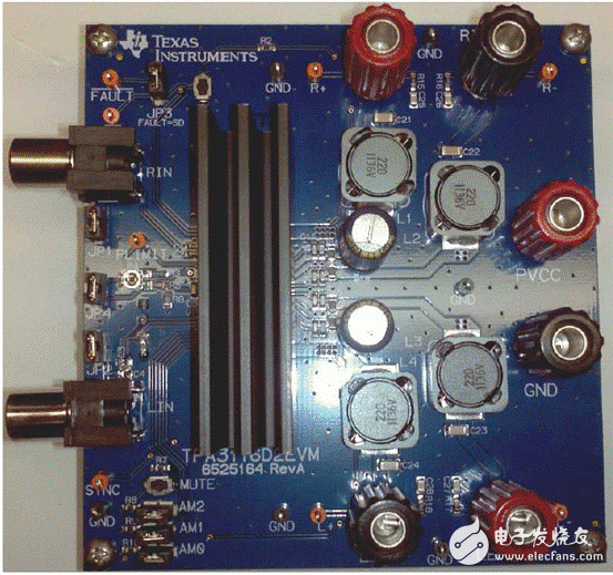
Figure 4. Outline of the evaluation board TPA3116D2EVM
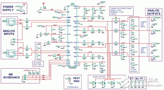
Figure 5. Evaluation board TPA3116D2EVM circuit diagram
Evaluation Board TPA3116D2EVM Bill of Materials:
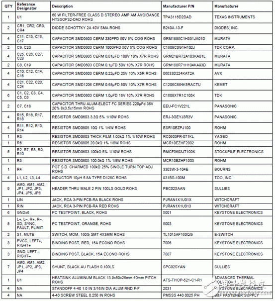
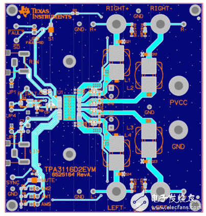
Figure 6. Evaluation Board TPA3116D2EVM PCB Layout
PCB Connectors: Backplane, Wire-to-Board, Board-to-Board Connectors
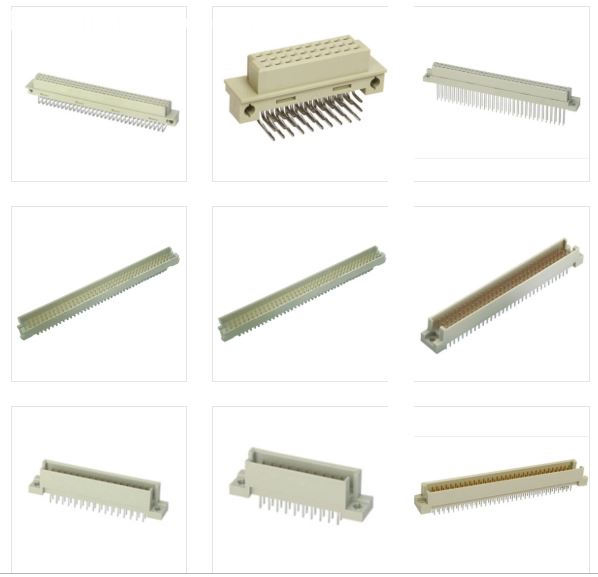
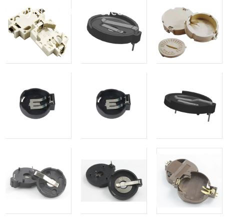
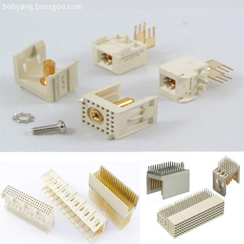
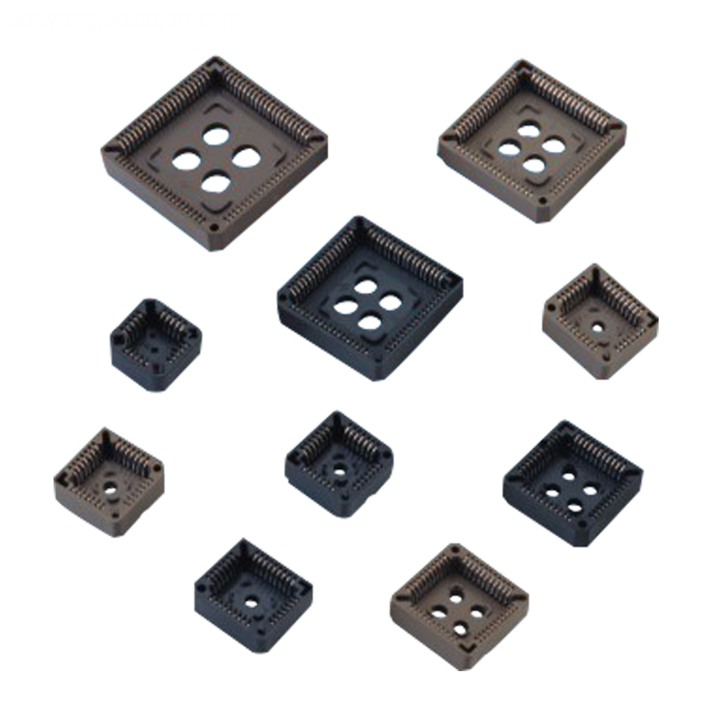
These types of connector systems are mounted or processed to a printed circuit board (PCB). There are a variety of PCB connectors and accessories best designed for specific uses. To name some, they include:Din41612 Connector,Board To Board Connectors,battery holders Clips Contacts,Future Bus Connectors,PLCC Connectors.
Din41612 Connector
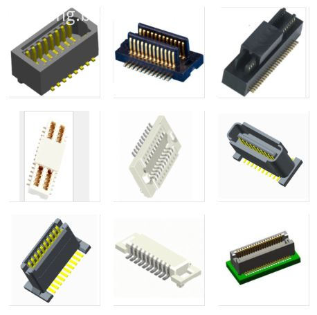
Board To Board Connectors
Battery Holders Clips Contacts
Future Bus Connectors
PLCC Connectors
1.ANTENK manufactures a wide range of application specific board stacking PCB connectors which were designed and built to specific customer requirements. Our experienced staff has developed custom products in a variety of contact styles, pitches and stacking heights. Our designs range from new concepts to duplicating existing market products identically or with improvements. Many desigsn are produced using automated manufacturing processes to increase reliability and provide significant cost savings.
2.Our products are widely used in electronic equipments,such as monitors ,electronic instruments,computer motherboards,program-controlled switchboards,LED,digital cameras,MP4 players,a variety of removable storage disks,cordless telephones,walkie-talkies,mobile phones,digital home appliances and electronic toys,high-speed train,aviation,communication station,Military and so on
What is a PCB Connector?
Printed Circuit Board connectors are connection systems mounted on PCBs. Typically PCB Connectors are used to transfer signals or power from one PCB to another, or to or from the PCB from another source in the equipment build. They provide an easy method of Design for Manufacture, as the PCBs are not hard-wired to each other and can be assembled later in a production process.
PCB Connector orientations
The term PCB Connector refers to a basic multipin connection system, typically in a rectangular layout. A mating pair of PCB Connectors will either be for board-to-board or cable-to-board (wire-to-board). The board-to-board layouts can give a range of PCB connection orientations, all based on 90 degree increments:
Parallel or mezzanine – both connectors are vertical orientation;
90 Degree, Right Angle, Motherboard to Daughterboard – one connector is vertical, one horizontal;
180 Degree, Coplanar, Edge-to-Edge – both connectors are horizontal orientation.
Other names for PCB Connectors
PCB Connectors can be known as PCB Interconnect product. Specific terms are also used for the two sides of the connection. Male PCB Connectors are often referred to as Pin Headers, as they are simply rows of pins. Female PCB Connectors can be called Sockets, Receptacles, or even (somewhat confusingly) Header Receptacles.
Din41612 Connector,Board To Board Connectors,Battery Holders Clips Contacts,Future Bus Connectors,PLCC Connectors
ShenZhen Antenk Electronics Co,Ltd , https://www.antenkcon.com
