Circuit Design of Joint Controller Based on DSP Humanoid Robot
The humanoid robot has mobility and has many degrees of freedom, including arms, neck, waist, legs, etc., which can complete more complex tasks. These joints must be connected together for unified coordinated control. The reliability and real-time performance of the system put forward higher requirements. In the past, the centralized control system used was highly centralized. Local failures may cause overall failure of the system and reduce the reliability and stability of the system. Therefore, a distributed control system is considered to realize the control function of the system.
Motor driver interface circuit
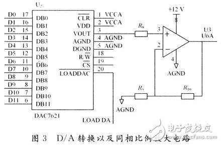
The drive's control mode can be divided into two types: speed control mode and position control mode (usually using a potentiometer as the position sensor of the motor). Here, its speed control mode is adopted, and the input command signal is an analog quantity of 0 to 10 V. Therefore, it is necessary to use a D/A conversion circuit to convert the digital output of the DSP output into an analog signal. The circuit diagram is shown in FIG. The DAC7621 is a 12 b parallel input D/A converter with a built-in reference source and an output range of 0 to 4.095 V. Its 12-bit input is connected to D0 to D11 in the DSP data bus. Its chip select input pin can be connected to the DSP I / O control line / IS. In order to obtain an analog signal of 0 to 10 V, a signal of 0 to 4.095 V is amplified by a factor of 2.5 by using a similar amplifier circuit composed of one operational amplifier in the LM358.

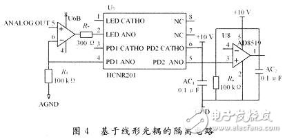
If the driver and controller are not isolated, spikes will destroy devices in the controller circuit, such as RAM. Therefore, an isolation circuit based on the linear photocoupler HCNR201 is designed, as shown in FIG.

The linear photocoupler HCNR201 can only function as an isolated current, and the input current and output current are linear. U6B is another operational amplifier in the chip LM358 of Figure 3. It converts the input 0~10 V voltage into a current signal within 20 mA and inputs the linear optocoupler HC-NR201. The HCNR201 output current is then converted to a 0 to 10 V voltage signal by a voltage follower consisting of a single supply rail-to-rail op amp, the AD8519, as an analog signal input to the driver. Obviously, the circuit on both sides of the HCNR201 should use different power sources and ground. The two op amps in the LM358 are powered from the 12 V supply of the controller input, while the AD8519 is powered from the 10 V supply provided at the driver input.
Incremental encoder signal processing circuit
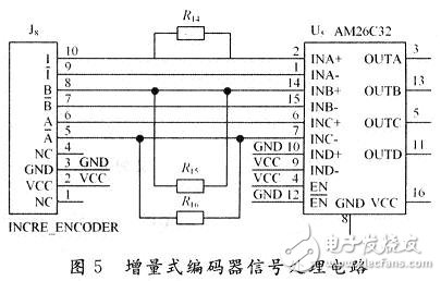
The incremental encoder signal processing circuit is shown in Figure 5. J8 is the signal input interface of MR encoder. It uses AM26C32 to convert the RS 422 differential signal outputted by MR encoder into three channels into TTL level, and obtains three signals of A, B and Z.

RS 485 bus communication circuit
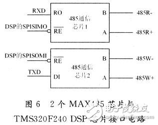
The RS 485 bus is a communication bus. The TMS320F240 DSP chip itself does not have an RS 485 bus interface. The two 485 communication chips MAX485 can convert the TTL level of the serial port RXD and TXD of the TMS320F240 to the RS 485 level, and the RXD of the TMS320F240DSP. And the TXD pin is connected to the pins of the first 485 communication chip RO and the second 485 communication chip DI, respectively. The SPISIMO and SPISOMI of the TMS320F240 DSP are connected to the enable pin RE of the MAX485 to control the data transmission port of the TMS320F240 DSP chip to be connected to the bus or separated from the bus. The circuit is shown in Figure 6.

Considering the calculation of the control algorithm of the robot arm control system and the multi-axis coordinated control, the architecture of distributed control based on RS 485 bus is adopted, as shown in the figure. The motion planning algorithm is implemented by the host computer, and the host computer will also communicate with the joint controllers via the RS 485 bus, which is responsible for the coordination of the joint controllers. Each joint controller and a motor, driver, and feedback device form a position servo system that is responsible for the specific control tasks of a joint variable of the robot arm.
Pharmaceuticals,2-Methyl- Propanoic Acid Monohydrate Price,2-Methyl- Propanoic Acid Monohydrate Free Sample,Pure 2-Methyl- Propanoic Acid Monohydrate
Zhejiang Wild Wind Pharmaceutical Co., Ltd. , https://www.wild-windchem.com
