Composition and design of semi-autonomous remote control mobile robot system using DSP
1 Composition of remote control mobile robot system
The system consists of three parts: remote control platform, wireless transmission network and local robot car. DSP is the core of local robot car control. TI company
The company's TMS320LF2407A chip has an improved Harvard structure system, adopts pipeline technology and other advantages, and uses high-performance static CMOS / technology to reduce the chip's operating voltage to 3.3V, which greatly reduces the chip's power consumption. The CPU has a very high processing speed, and the frequency can reach 40 MHz. Many complex algorithms are implemented in the system control. In addition, it also integrates powerful peripherals such as 32 KB flash memory, 16 pulse width modulation (PWM) channels, a CAN module, and an ultra-high-speed 500 ns 10-bit analog-to-digital converter (ADC).
The whole system takes F2407A as the core of the controller, and expands the human-machine interface (LCD display and button) module, environmental camera module, drive motor module, photoelectric encoder feedback module, and GPRS human-machine interaction module of the robot body. The block diagram of the control system structure is shown in Figure 1.
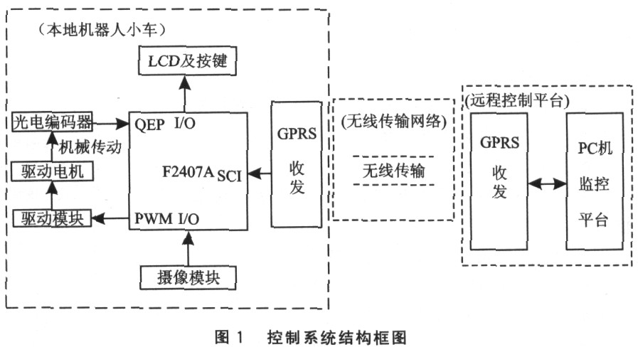
1.1 The positioning module of the robot car
The robot positioning module is mainly composed of a motor and its driving circuit, a mechanical transmission system and a photoelectric encoder. Gear drive is used between the driving wheel and the photoelectric encoder, the transmission ratio is i, the resolution of the photoelectric encoder is N (that is, the number of pulses output per revolution of the encoder), and the radius of the driving wheel is r, each time the encoder outputs One pulse, the distance the corresponding wheel travels on the ground is 
The motor control adopts the pulse width modulation (PWM) speed regulation method, and the feedback information of the photoelectric encoder is collected by the quadrature encoding pulse (QEP) circuit provided by the DSP to perform closed-loop PID control on the motor. Using the QEP circuit to capture the feedback signal of the photoelectric encoder can simplify the preparation of the program, while using the PID control principle, it can improve the control accuracy and stability of the system.
The schematic diagram of the motor drive is shown in Figure 2. The driving main chip is L293B. The L293B DC motor drive chip allows a voltage range of 4.5 ~ 36V, with a quadruple push-pull (double H-bridge integrated circuit) drive circuit, and two channels can provide l A drive current to each motor. And, if the chip is overheated, the chip can automatically shut down to protect the system from damage. When A direction and B direction are high level, the current of motor A and B flows from 3 feet to 6 feet and 11 feet to 14 feet respectively, and the motor rotates forward; otherwise, when A and B directions are low level, the motor current From 6 feet to 3 feet and 14 feet to 11 feet respectively, the motor reverses. At this time, you can use the PWM control chip on-off time ratio of the motor enable pin to adjust the speed of the motor. The F2407A DSP chip supports PWM output, so you can easily adjust the speed of the drive motor.
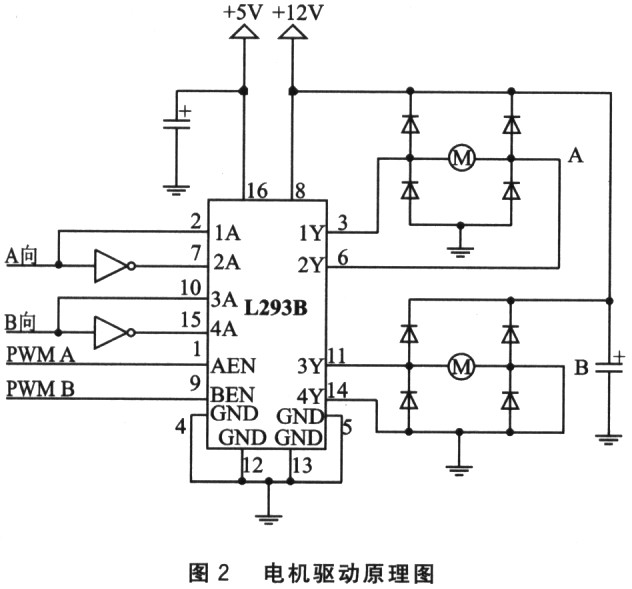
Because the DSP chip has its own quadrature encoder capture module, the circuit design of this part is relatively simple. The orthogonal pulse signal output by the photoelectric encoder is stabilized by the NOT gate, and the QEP circuit entering the DSP chip is captured and recognized by the CPU, and then the recognized information is used as the feedback input of the PID control algorithm.
1.2 LCD display and camera module
The data format of the LCD display module and the camera module are 8 bits, and the interface with the microcontroller such as the single chip is flexible and simple. The camera module can output compressed images in JPEG format, so the amount of data is small, reducing the burden of data processing by the controller, while shortening the time for GPRS to transmit one frame of image, and real-time performance is better. F2407A provides a rich I / O interface, and the I / O port can be used to write and read data to the LCD module and camera module. Since the data of the LCD module is written, and the data of the camera module is read, the same set of I / O ports can be multiplexed in time-sharing without conflict. By design, the enable ends of these two modules are controlled with different control lines to achieve time-division multiplexing, and all use DSP I / OPB0 ~ I / OPB7 as their data interfaces.
2 GPRS wireless image transmission
GPRS (General Packet Radio Selvice) is a packet-based wireless communication service. It is a new GSM data service that can provide wireless packet data access services to mobile users. GPRS mainly provides a connection between mobile users and remote data networks, thereby providing high-speed wireless IP and wireless X.25 services to mobile users.
The advantages of GPRS data transmission are:
â—‡ High transmission rate;
â—‡ Real-time online;
â—‡ Charge according to flow;
â—‡ Not affected by distance;
â—‡ Quick login.
2.1 GPRS networking
In this system, the use of GPRS mobile communication network to achieve two-way transmission of information. The data transmitted from the robot car to the remote monitoring platform mainly includes on-site image information and the current positioning information of the car; the remote monitoring platform transmits the command information to the car.
GPRS image acquisition module is composed of acquisition terminal, DSP peripheral interface, GPRS transceiver, PC interface and monitoring center software. After the image data is collected, it is transmitted to the GPRS transceiver 1 by the DSP serial port, and the transceiver 1 sends the image data through the GPRS wireless network, and then the GPRS transceiver 2 transmits the received image data to the serial port of the PC, and then monitors The center software reads data from the serial port of the PC and finally displays it on the interface of the monitoring center to complete real-time monitoring on site. The structure diagram of GPRS networking mode is shown in Figure 3.

2.2 Flow chart of image data acquisition program
The image acquisition process includes two parts: DSP serial communication initialization and image data transmission. The monitoring center issues an image acquisition instruction, transmits the signal to the DSP serial port via the GPRS module, starts the interrupt service of the DSP serial port, collects camera image data, and sends the data to the remote monitoring center via the GPRS module to complete the frame image acquisition cycle. The image data acquisition program flow is shown in Figure 4.
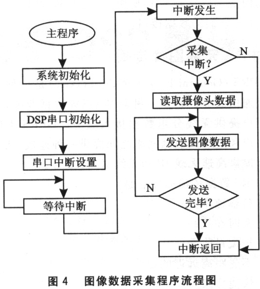
The software design of the DSP chip supports C language, assembly language, and mixed programming of both. Because this system involves image data processing, the realization of motor PID control algorithm and LCD display, etc., the program is complicated and the programming workload is large. The method can better combine the advantages of C language and assembly language to write higher efficiency program code.
2.3 Data transfer protocol
The data transmission protocol is divided into two parts, one part is the control command sent by the C computer to the DSP, and the other part is the feedback information sent by the DSP to the PC. The data transmission format is in the form of data packets, so the data that needs to be sent must be packaged each time. The specific data packet types are as follows;
![]()
The units of the data package are defined as follows:
â—‡ The start flag is a byte, with a fixed value of 0x00;
â—‡ The control word is a byte, and the value range is 0x0l ~ 0xff. For the specific data types, see 2.3.1 and 2.3.2;
â—‡ The data length unit is two bytes, the value range is 0x0001 ~ 0xffff, in which the low byte is in front and the high byte is in the back, indicating the number of bytes of data to be sent;
â—‡ The number of bytes of the data unit to be sent is uncertain, and the content is determined by the specific content of the data sent;
â—‡ The data verification unit is a byte, the value of each byte of the data to be sent is different or derived;
â—‡ The end flag is a byte, and the fixed value is 0x01.
2.3.1 Data transfer protocol from PC to DSP
The types of data sent from the PC to the microprocessor DSP include image acquisition commands, given robot walking types, and response feedback commands. After receiving various instructions sent by the PC, the DSP reads the data content, then XORs each byte of the data content, and then compares the value obtained by the XOR with the received check code, if they are equal Then feedback to the PC that the data is received correctly, and then transfer to the interrupt service program of the corresponding instruction; if they are not equal, feedback the data reception error to the PC and apply for re-sending the instruction. The definition of each instruction is listed in Table 1.
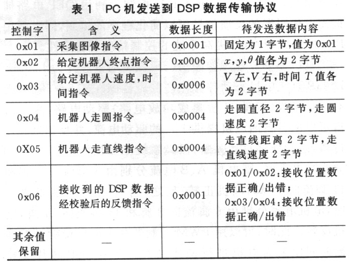
2.3.2 Data transfer protocol from DSP to PC
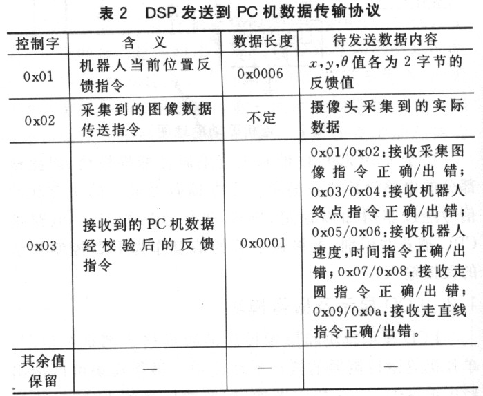
The data types sent by the DSP to the PC mainly include the robot current position feedback data, image data, and DSP response feedback commands. After the PC receives the data, the verification process is the same as the DSP process described in the previous section after receiving the data. When the robot car is walking, it will send its current position data to the PC at regular intervals to achieve real-time path tracking. At the same time, when the DSP receives the image acquisition instruction from the host computer, it will perform image acquisition and then collect The received image data is sent to a PC for image display, realizing real-time monitoring of the environment information around the robot car. Specific instruction definitions are listed in Table 2.
3 Experimental results
The software of the monitoring center is compiled with Delphi advanced language. Enter Ol in the "Control Command" column (Ol stands for the image capture command), click "Send", and then the "Image Monitor" column of the monitoring interface will display the remote environment information collected by the camera.
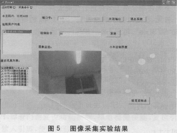
During the experiment, the resolution of the camera was adjusted to 320 × 240, and the two GPRS transceivers were at the two ends of the room about 4 m apart. Figure 5 shows the experimental results. The experimental results show that the semi-autonomous mobile robot remote system based on GPRS mobile communication network and DSP technology has achieved the expected results. At the same time, it is also found in the experiment that the real-time nature of GPRS transmission data is limited. Although the theoretical transmission rate is as high as 171 kb / s, it is actually affected by many factors. The actual rate is low, and a frame of 3K JPEG format is transmitted. The image takes about 3O ~ 60s. Therefore, how to further improve the real-time performance of the system is the biggest challenge facing this system.
All In One Pc,All In One Pc Gaming,All In One Pc As Monitor,All In One Pc For Business
Guangzhou Bolei Electronic Technology Co., Ltd. , https://www.nzpal.com
