Design of wireless communication hardware module based on CC2430
With advances in technologies such as microelectronics, juice computing, and wireless communications, wireless sensor networks are ranked among the 21 most influential technologies of the 21st century and one of the top 10 technologies that have changed the world. It monitors, senses, and collects information from various environments or monitored objects in real time and processes them. The sensor node is the basic unit that constitutes the wireless sensor network and is the basic platform that constitutes the wireless sensor network.
ZigBee is an emerging short-range, low-rate wireless network technology. It is a set of technical standards related to networking, security and application software developed based on the IEEE 802.15.4 wireless standard. It has the advantages of low power consumption, low cost, security, flexible working frequency, etc. The wireless sensor ZigBee network is formed by sensors and sensors, which makes the automatic data collection, analysis and processing easier, and can be an important part of decision support system.
1 CC2430 and ZigBee protocol stack architectureThe CC2430 is a true system-on-chip (SoC) CMOS solution that improves performance and meets the low-cost, low-power requirements of the ZigBee-based 2.4 GHz ISM band application. It combines a high-performance 2.4GHz DSSS (Direct Sequence Spread Spectrum) RF transceiver core with an industrial-grade compact and efficient 8051 controller. The CC22430 integrates a ZigBee radio frequency (RF) front end, memory and microcontroller on a single chip, using an 8-bit MCU (8051) with 32/64/128 KB of programmable flash and 8 KB of RAM, plus analog/digital Converter (ADC), timer (TImer), AES128 safety coprocessor, watchdog TImer, sleep mode timer for 32 kHz crystal, power-on reset circuit, power-down detection circuit, and 21 Program the I/O pin. The object code of the CC2430's 8051 core is compatible with the standard 8051 microprocessor and can be developed using the standard 8051 assembler and compiler. The 21 programmable I/O pins can be software-set to set the bits and bytes of a set of SFR registers, making these pins a normal I/O port or as a peripheral to an ADC, timer, or USART component. I/O port is used.
The ZigBee protocol stack consists of a set of sublayers, each layer providing a specific set of services for its upper layer: the data entity provides the data transfer service, and the management entity provides all other services. Each service entity provides a service interface to the upper layer through a Service Access Point (SAP), and each SAP provides a series of basic service instructions to perform the corresponding functions. The architecture model of the ZigBee protocol stack is shown in Figure 1. The IEEE 802.15.4 standard defines the physical layer (PHY) and the medium access control sublayer (MAC); the ZigBee Alliance defines the network layer and the application layer (APL). The design of the frame.
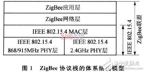
The ZigBee protocol stack was released in 2004 with the first edition, called ZigBee2004. ZigBee2004 is a full-source code stack. This protocol stack already has the concept of a network and can perform some simple communication. However, it can only form a string network and a star network. If you need to set up a mesh network, you must add a program, and it is not ideal in terms of security and routing. The ZigB-ee2006 protocol stack solves the problem of network networking well. The security of the entire protocol stack is better, the hierarchy is stronger, the power consumption is improved, and the mesh network is realized. In the ZigBee-2006 protocol stack, the underlying drivers of the CC2430 have been fully cured in the protocol stack and can be called directly.
In summary, the CC2430 chip is selected as the hardware core chip of the wireless communication module, and the software part selects the ZigBee2006 protocol stack to implement the communication function between the wireless modules.
2 hardware designAs an important data transmission channel in the monitoring system, the wireless communication part not only needs to implement the data receiving and transmitting functions between the wireless communication modules, but also needs to provide the data interface and the terminal data collecting part and the local main control system for connection. The system structure is shown in Figure 2.
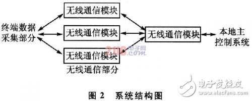
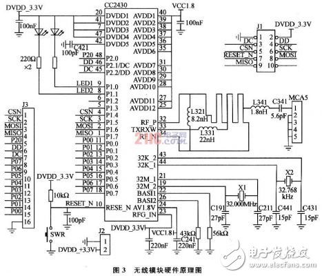
Figure 3 shows the hardware schematic of the wireless module. The circuit uses CC2430 chip as the core CPU of the wireless sensor network node. A 32.768 kHz quartz resonator (X2) and two capacitors (C441 and C431) are used to form a 32.768 kHz crystal oscillator circuit; a 32 MHz quartz resonator (X1) and two capacitors (C191) are selected. And C211) constitute a 32 MHz crystal oscillator circuit. The voltage regulator supplies power to all internal supplies that require 1.8 V. Capacitors C241 and C421 are used as decoupling capacitors for power supply filtering to improve chip operation stability. In the circuit, J1 is a 10-pin JTAG emulator interface, J2 is a 3.3 V power interface, and J3 is a CC2430 chip expansion output port. The SPI port and the entire PO I/O port are reserved on the extended output port. Two LED indicators are designed as circuit debugging indicators. Using an unbalanced antenna, in order to make the antenna performance better, an unbalanced transformer is connected between the antenna and the CC2430. The balun consists of capacitor C341 and inductors L321, L331, L341 and a PCB microwave transmission line. The entire structure meets the requirements of RF input/output matching resistor (50 Ω).
3 protocol stack software designSoftware development software environment: IAR 7.30B, data analyzer, serial debugging tools and hardware driver software; hardware environment: computer, CC2430 development board.
The system software is based on the ZigBee2006 protocol stack provided free of charge by TI/Chipcon and is based on the GenericApp routine in the ZStack-1.4.3-1.2.1 release. The basic functionality of the GenericApp example is very complete, and wireless network data transmission is implemented on ZStack. Routines have no extra features, so they are typical ZStack templates, which provide users with a generic template through which they can build their own applications. Therefore, the method of establishing a project is mainly to modify the application layer (APP) program.
The wireless communication module realizes connection with the data collection part and the local main control part through the serial port respectively. Therefore, the main function of the application layer software is to realize the transmission and reception of serial data and wireless network data transmission. A real-time operating system is embedded in the ZStack program for unified scheduling of network composition, node joining, data transceiving and other functions. The working mechanism is mainly the multi-tasking event running mechanism. For the same task, there may be multiple events, and different event processing needs to be performed. For convenience, the event handler for each task is uniformly implemented in an event handler, and then the event handler of a task is called according to the task ID number (task id) and the specific event of the task. After entering the event processing function of the task, it is determined according to the event which event of the task occurs, and then the corresponding event processing is executed. The specific process of the task processing part is shown in Figure 4.
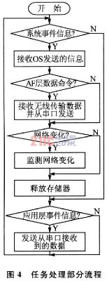
The serial port part and the wireless receiving and transmitting part of the program are described in detail below.
3.1 Serial Port Program
(1) Serial port initialization
Mainly set the halUARTCfg_t structure member value:
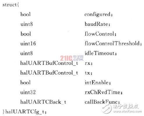
By assigning a value to halUARTCfg_t, you can set the baud rate, number of characters, data bits, stop bits, parity bits, and hardware flow control. Call-BackFunc is a custom setting serial port callback function, that is, once the serial port has data transfer, OSAL will automatically go to the custom callback function to perform a custom operation.
(2) serial port callback function
First call the Hal_UART_RxBufLen (uint8 port) function to determine the length of the serial data, then call HalUARTRead (uint8 port, uint8*buf, uintl6 len) to read the serial data to the custom serial data buffer, and call osal_set_event (byte task_id, UINTl6 The event_flag) function sends an event signal to perform wireless transmission of data.
3.2 Wireless receiving and transmitting part of the program
(1) Wireless reception
When data is sent wirelessly to the application layer, the application layer sends an AE_INCOMING_MSG_CMD message event.
Case AF_INCOMING_MSG_CMD:
GenericApp_MessageMSGCB(MSGpkt);
Break:
This means that the AF_INCOMING_MSG_CMD message event is received, and then the message processing function GenericApp_MessageMSGCB (MSGpkt) that receives the message event is called to start receiving data and send the received data by using the serial port HalUARTWrite (uint8 port, uint8*buf, uintl6 len) write function. .
(2) Wireless transmission
In the serial port callback function, when the serial port has data input, the application layer will send a GENERICAPP_SEND_MSG_EVT message event.

Call the GenericApp_SendThmMessage() data sending function, which is the AF_DataRequest() function in the ZigBee2006 protocol stack provided by TI/Chipcon. The specific form is as follows:

In this paper, CC2430 is used as the main body to design the hardware of the wireless communication module, and the ZigBee2006 protocol stack provided by TI/Chipcon is used as the software development platform. Through experimental verification, the designed hardware nodes basically meet the project requirements. After debugging, the serial port can correctly receive and send data, and can realize communication and data transmission of multiple wireless nodes (1 coordinator, 3 terminal devices) at about 50 m, and test correctly through the computer serial port debugging software.
The utility model relates to a medical atomization treatment and humidifying device belonging to the technical field of medical equipment and household appliances.
Professional Medical Atomization manufacturer is located in China, including Medical Vape,Dose Control Vape Pen,Supersonic Wave Vape, etc.
Medical Atomization,Medical Vape,Dose Control Vape Pen,Supersonic Wave Vape
Shenzhen MASON VAP Technology Co., Ltd. , https://www.e-cigarettefactory.com
