DS26303 LIU initialization and configuration
Abstract: This application note describes how to properly configure the DS26303 T1 / E1 / J1 line interface unit (LIU), and contains C-style sample code that can help designers quickly implement basic system operations and facilitate initial software development.
Introduction When developing software for a newly designed telecommunications system, the most difficult task is to implement basic equipment operations. The large number of functions and multi-port operation of the DS26303 transceiver make software development more complicated. In order to facilitate the initial system development, Maxim provides C-style sample code, which can initialize the device in T1 or E1 mode. Software developers only need to modify the code for the required operation or write functions related to a specific system. Once the code is compiled, it can be loaded into the system for testing and evaluation. It should be noted that there are two versions of DS26303, namely DS26303-120 and DS26303-75. The difference between them is small and only affects a few settings, so you need to figure out which device is used in the design.
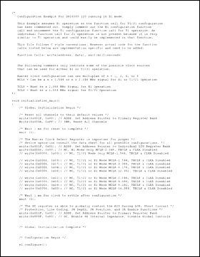
Code Example The example code shown in Figure 1 can be compiled correctly for the target system after a slight modification. 'write (address, data)' and 'wait (milliseconds)' two function call processes are system-dependent, so they need to be written according to the microprocessor used. This code assumes that the device is mapped to a 16-bit local bus (address offset 0x0000), and the device's data bus is 8 bits. For other cases, you need to modify the code or write function calls to solve. This code also contains a variety of different settings for certain registers, which provides developers with multiple choices of parameters such as clock frequency and line coding. Although it contains a lot of basic functions, the code is not complete. When you need to implement other additional functions, please refer to the data.

Download the complete code (TXT, 16kB)
Introduction When developing software for a newly designed telecommunications system, the most difficult task is to implement basic equipment operations. The large number of functions and multi-port operation of the DS26303 transceiver make software development more complicated. In order to facilitate the initial system development, Maxim provides C-style sample code, which can initialize the device in T1 or E1 mode. Software developers only need to modify the code for the required operation or write functions related to a specific system. Once the code is compiled, it can be loaded into the system for testing and evaluation. It should be noted that there are two versions of DS26303, namely DS26303-120 and DS26303-75. The difference between them is small and only affects a few settings, so you need to figure out which device is used in the design.
Code Example The example code shown in Figure 1 can be compiled correctly for the target system after a slight modification. 'write (address, data)' and 'wait (milliseconds)' two function call processes are system-dependent, so they need to be written according to the microprocessor used. This code assumes that the device is mapped to a 16-bit local bus (address offset 0x0000), and the device's data bus is 8 bits. For other cases, you need to modify the code or write function calls to solve. This code also contains a variety of different settings for certain registers, which provides developers with multiple choices of parameters such as clock frequency and line coding. Although it contains a lot of basic functions, the code is not complete. When you need to implement other additional functions, please refer to the data.

Download the complete code (TXT, 16kB)
A manual pulse generator (MPG) is a device normally associated with computer numerically controlled machinery or other devices involved in positioning. It usually consists of a rotating knob that generates electrical pulses that are sent to an equipment controller. The controller will then move the piece of equipment a predetermined distance for each pulse.
The CNC handheld controller MPG Pendant with x1, x10, x100 selectable. It is equipped with our popular machined MPG unit, 4,5,6 axis and scale selector, emergency stop and reset button.
Manual Pulse Generator,Handwheel MPG CNC,Electric Pulse Generator,Signal Pulse Generator
Jilin Lander Intelligent Technology Co., Ltd , https://www.landerintelligent.com
