Electrical schematic, electrical layout and electrical installation wiring diagram - Solutions - Huaqiang Electronic Network
The electrical control circuit basic electrical control system diagram generally has three types: electrical schematic diagram, electrical layout diagram and electrical installation wiring diagram.
The focus here is on the electrical schematic.
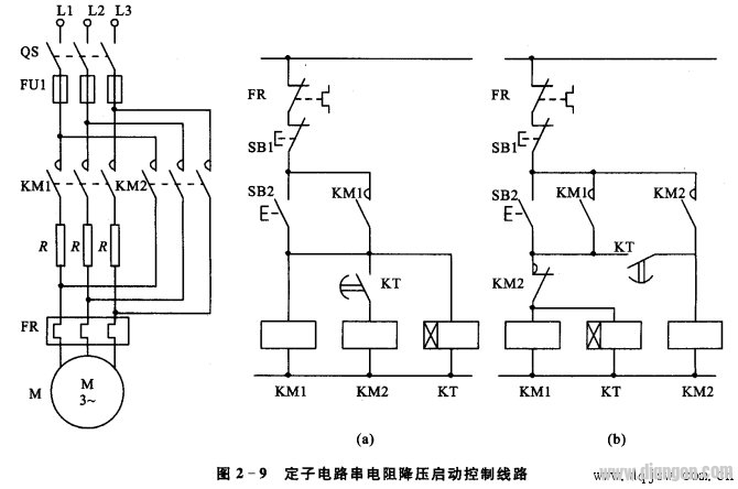
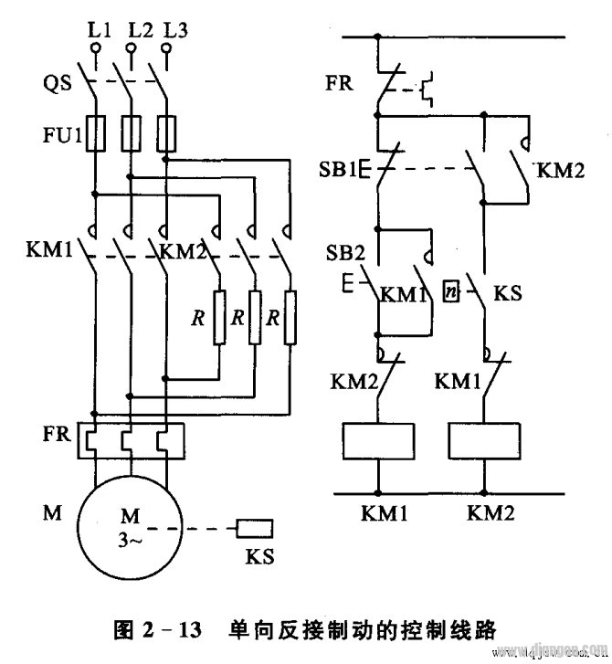
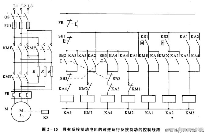
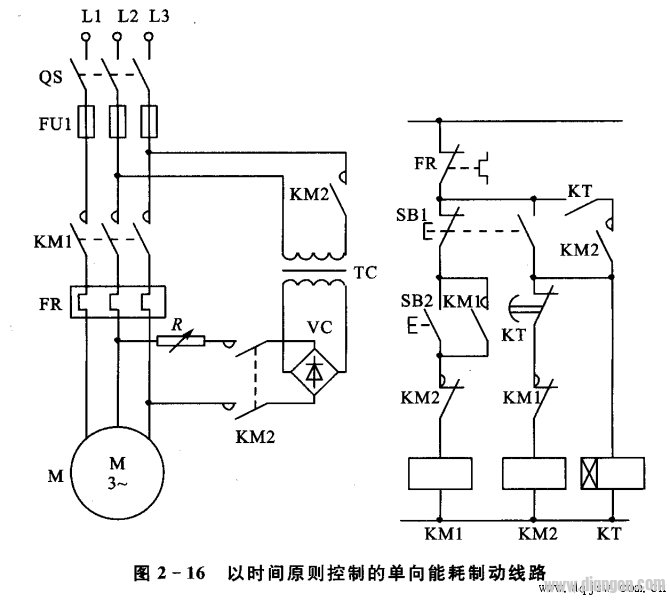
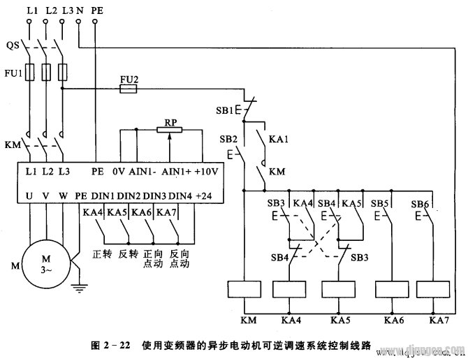
The purpose of the electrical schematic is to facilitate the reading and analysis of the control circuit. It should be drawn in the form of electrical components according to the principle of simple structure and clear hierarchy. It includes the conductive parts and terminals of all electrical components, but does not draw according to the actual arrangement position of the electrical components, nor does it reflect the actual size of the electrical components.
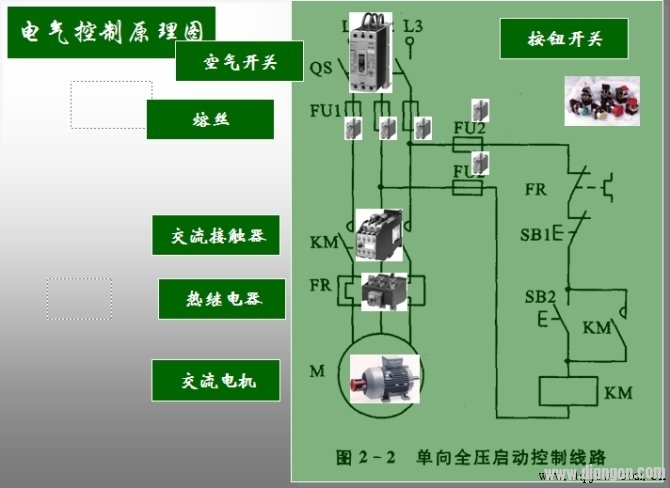
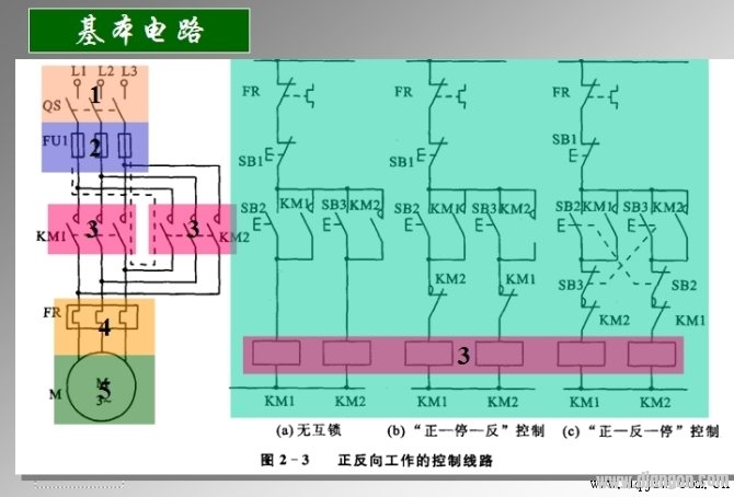
The electrical schematic diagram is generally divided into two parts: the main circuit and the auxiliary circuit (control circuit).
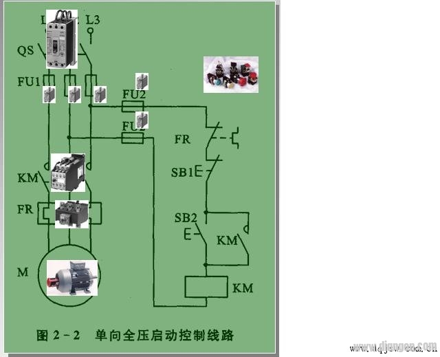
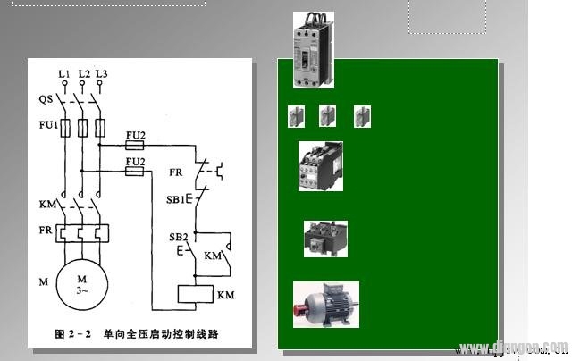
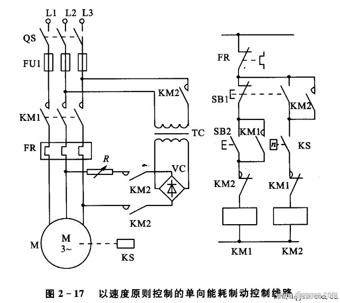
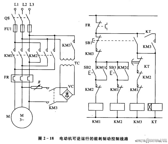
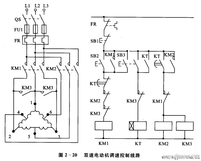
The main circuit is a part of the electric control circuit through which a large current passes, and includes electrical components connected from the power source to the motor; generally consists of a combination switch, a main fuse, a contact main contact, a thermal element of the thermal relay, and a motor.
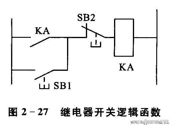
The auxiliary circuit is a circuit other than the main circuit in the control circuit, and the current flowing through it is relatively small and the auxiliary circuit includes a control circuit, a lighting circuit, a signal circuit, and a protection circuit. The control circuit is composed of a button, a coil of a contactor and a relay, an auxiliary contact, a thermal relay contact, and a protective electrical contact.
All electrical components in the electrical schematic diagram shall be represented by graphic symbols and text symbols uniformly specified in the national standard.
The layout of electrical components in the electrical schematic diagram The layout of electrical components in the electrical schematic diagram should be arranged according to the principle of easy reading. The main circuit is arranged on the left or above the drawing, and the auxiliary circuit is arranged on the right or below the drawing. Regardless of the main circuit or the auxiliary circuit, they are arranged according to functions, and are arranged from top to bottom and left to right as much as possible in the order of action.
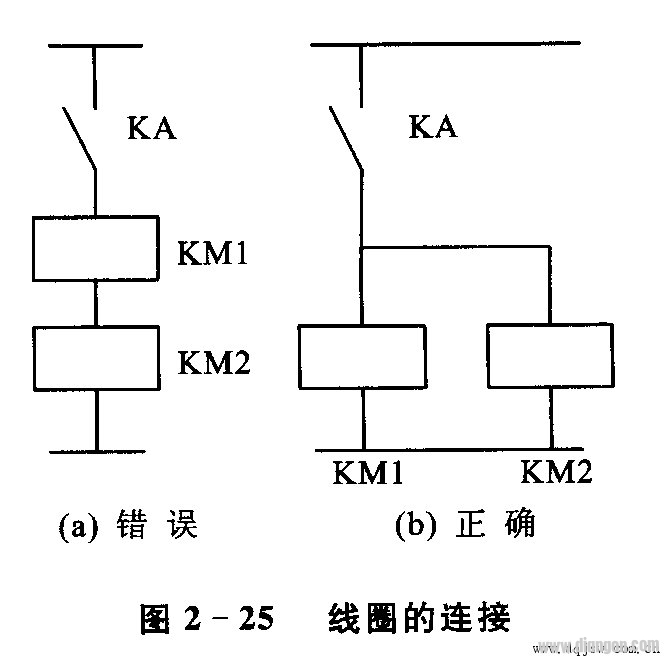
In the electrical schematic diagram, when different parts of the same electrical component (such as coils, contacts) are dispersed in different positions, in order to indicate that they are the same component, uniform text symbols are to be marked at different parts of the electrical component. For similar devices, the number is added after the text symbol to distinguish it. For example, two contactors can be distinguished by KMI and KMZ text symbols.
In the electrical schematic, the movable parts of all appliances are drawn in a state where there is no power or no external force.
For the contacts of the relay and the contactor, the state is drawn according to the state when the coil is not energized, and the controller draws the state when the handle is at the zero position; for the state where the button, the travel switch, and the like are not subjected to the external force, the state is drawn. Out.
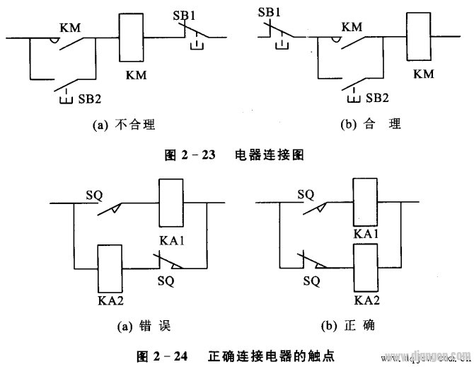
In the electrical schematic, the lines should be minimized and the lines should not be crossed. When there is electrical connection between the wires, draw a solid dot at the intersection of the wires. According to the layout requirements, the graphic symbol can be rotated and rotated, generally rotated 90o counterclockwise, but the text symbol can not be inverted.
The number of 1, 2, 3, etc. above the dividing drawing of the drawing area is the number of the drawing area. It is for the convenience of retrieving the electrical circuit, and it is convenient to read and analyze to avoid missing settings. The area number can also be set below the figure.
The text below the number of the area indicates the function of the corresponding component or circuit below, so that the reader can clearly know the function of a certain component or part of the circuit to understand the working principle of all circuits.
Index of symbol position
q The index of the symbol position is a combination index method of the figure number, the negative order and the area number. The composition of the index code is as follows:
q The figure number refers to the number of each book when the electrical schematic of a device is bound according to the function. It is generally indicated by a number.
q When each symbol element related to a component appears on a drawing with a different drawing number, and when each drawing number has only one sheet of drawing, the “page number†and the separator “·†may be omitted from the index code.
q When the symbol elements related to a component appear on the drawing of the same drawing number, and the drawing number has several drawings, the “drawing number†and the separator “/†may be omitted.
q When each symbol element associated with a component appears in a different area of ​​a sheet, the index code is only represented by the “picture areaâ€.
q The “8†below the KA normally open contact in Figure 9 in Figure 2-1 is the simplest index code. It points out the coil position of the relay KA in the map area
q Figure 2-1 Contactor KM Coil and Relay The text below the KA coil is the index of the corresponding contact of contactor KM and relay KA.
q In the electrical schematic, the affiliation of the contactor and relay coils to the contacts is shown using the image to the right. That is, below the corresponding coil in the schematic diagram, the graphical symbol of the contact is given and marked below.

3.2V Battery Cells,Prismatic Phosphate Lithium Batteries,3.2V 202Ah,3.2v lifepo4 battery,3.2V LifePO4 Lithium Battery Pack
Jiangsu Zhitai New Energy Technology Co.,Ltd , https://www.jszhitaienergy.com
