G instruction programming application and instruction - Database - Database & Sql Blog Articles
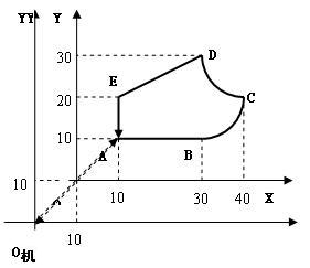
Example: The workpiece profile ABCDEA consists of three straight segments and two arc segments. XO work Y is the workpiece coordinate system for programming, and the dimensions of the parts are marked in absolute coordinates. The O machine is the origin of the machine. After the part is mounted on the machine, the workpiece offset value is measured as shown below.

G92 X-10 Y-10
N01 G90 G17 G00 X10 Y10 LF
N02 G01 X30 F100 LF
N03 G03 X40 Y40 I0 J-10 LF
N04 G02 X30 Y30 I0 J-10 LF
N05 G01 X10 Y20 LF
N06 Y10 LF
N07 G00 X-10 Y-10 M02 LF
N01 G91 G17 G00 X20 Y20 LF
N02 G01 X20 Y0 F100 LF
N03 GO3 X10 Y10 IO J-10 LF
N04 G02 X-10 Y10 I0 J-10 LF
N05 G01 X-20 Y-10 LF
N06 Y-10 LF
N07 G00 X-20 Y-20 M02 LF
First, the coordinate instruction
1. G90 - absolute coordinate command
Indicates that the programming size in the block is given in absolute coordinates.
2. G91 - relative coordinate instruction
Indicates that the programming size in the block is given by relative coordinates.
Generally only one coordinate instruction is used in the same block. However, there are also numerical control systems (lathes) that use two kinds of coordinate programming in one block. In this case, the address characters of the code words representing the coordinate size use different letters, such as: absolute coordinates with X, Y, Z; relative coordinates Use U, V, W.
3. G92—Preset register command set by coordinate system
When programming with absolute coordinates, the relationship between the machine coordinate system and the workpiece coordinate system needs to be set with the G92 command. That is, the offset value of the workpiece origin (X=-10, Y=-10 in the example) is registered in the register of the CNC system by the G92 command (G92 X-10 Y-10). This sets the sitting position of the machine origin relative to the workpiece coordinate system. Before machining, manually or automatically return the machine to the origin (the tool's tool point is aligned with the machine origin). When the program runs the first block, the offset value is automatically added to the coordinate shift command of the first block. In the middle, the tool runs relative to the workpiece to the end of the first block.
Using the G92 command eliminates machining errors caused by inaccurate mounting positions on the machine.
4. G17, G18, G19--plane command
Indicates the function of machining in a certain plane. G17—in XY, G18—in ZX, G19—in YZ, the writing of coordinate address characters in the block should be consistent with the plane command. G17 GOO X--- Y---, G18 G00 X- Z---. G19 GOO Y--- Z---.
Second, fast positioning instructions ---- G00
G00 commands the tool to move from the current positioning point to the next positioning point specified by the program block from the current positioning point and the maximum movement speed preset by the CNC system.
The first program in the example, G90 G17 G00 X10 Y10, the current positioning point O (execution of the tool position before this block), the next positioning point is point A (X=10, Y=10), the tool The relative workpiece moves from the O-point to the point A of the absolute coordinate value (10, 10) in the workpiece coordinate system. The next anchor point can also be specified with relative coordinates: G91 G17 G00 X20 Y20.
The feedrate F--- cannot be specified in the G00 block.
Third, the linear interpolation instruction --- G01
G01 command two coordinates (or three coordinates) have been linked, according to the feed speed F--- specified in the block, from the current position, linear interpolation feed to the next position specified in the block, Machining plane (space) straight lines.
In the example, the 2nd, 5th, and 6th blocks. G01 X30 F100 Current position A (starting point of the line to be interpolated, known), the absolute coordinate value of the next position B in the workpiece coordinate system (X30, Y10) (end point of the line), given in the block. F100 is the specified feed rate (must be given). The next position can also be given by relative coordinates, G01 X20 F100.
Fourth, circular interpolation command --- G02, G03
G02(G03)G01 commands the two coordinates to be linked, according to the feedrate F--- specified in the block, from the current position (the starting point of the arc), the clockwise (counterclockwise) circular interpolation feed Machining the arc to the next position (the end point of the arc) specified in the block.
Programming format: G90 G17 G02 X--- Y--- I--- J--- F--- LF
G18 X--- Z--- I--- K---
G91 G19 G03 Y--- Z--- J--- K---
Given the start point, end point and center of the arc, clockwise interpolation from the starting point to the end point and counterclockwise interpolation from the starting point to the end point are two different arcs, so two commands G02 and G03 are required to command the arc. The forward and backward directions of the interpolation are as follows: Observed in the negative direction of the coordinate axis perpendicular to the plane of the arc, the motion of the arc from the start point to the end point is a clockwise circular interpolation when clockwise (G02) Counterclockwise circular interpolation (G03) when counterclockwise.
I, J, and K specify the coordinates of the center of the circle. The value is the component value of the vector of the starting point of the arc relative to the center of the circle on the X, Y, and Z coordinates or the component of the vector of the center of the arc relative to the starting point of the arc at the X, Y, and Z coordinates. Instructions are described in the CNC system programming manual.
Some CNC systems can also specify the center coordinates using the arc radius R. This is, if the central angle of the arc is less than or equal to 180 degrees, the value of R is positive, otherwise, it is negative.
The circular circle can be used to process the whole circle. This is the same as the absolute coordinate value of the starting point and the ending point, and the relative coordinate value is zero.
Five, tool radius compensation instructions --- G40, G41, G42
The programming size of the CNC machining program is generally the workpiece contour size. When machining a plane profile with a cylindrical milling cutter, the path of the tool center (tool point) should be a path that is offset from the contour normal by a tool radius. The tool radius compensation command must be used at this time.
The tool radius compensation command automatically calculates the tool center path according to the size programmed according to the workpiece contour in the machining program and the tool center offset (tool radius r+δ) stored in the CNC system memory, thereby controlling the tool center edge. This trajectory motion is processed.
If there is no tool radius compensation function, it must be programmed according to the tool center path. Thus: (1) Before the programming, the tool center path must be calculated according to the workpiece contour size and the tool center offset, thus increasing the programming workload, low programming efficiency, and error. The probability is great. (2) When the tool changes its radius due to replacement and re-grinding, as the tool path changes, it is necessary to recalculate the tool center path and reprogram the machining program. This will be cumbersome and affect the normal and smooth production.
With the tool radius compensation function, not only can solve the above problems, but also can use this function: (1) Conveniently control the machining allowance of roughing, and the same machining program is used for separate finishing. (2) When the size of the machined part is positively out of tolerance, the machining error can be corrected by correcting the tool center offset.
G41---Tool radius left compensation command, observed along the tool advance direction, the tool is biased to the left of the workpiece contour.
G42---Tool radius right compensation command, observed along the tool advance direction, the tool is biased to the right of the workpiece contour.
G40----tool compensation function cancellation command
G92 X-10 Y-10
N01 G90 G17 G00 G42 D01 X10 Y10 LF
N02 G01 X30 F100 LF
N03 G03 X40 Y40 I0 J-10 LF
N04 G02 X30 Y30 I0 J-10 LF
N05 G01 X10 Y20 LF
N06 Y10 LF
N07 G00 G40 X-10 Y-10 M02 LF
D01 is the memory address of the CNC system pre-stored tool center offset. Before machining, manually input the tool offset to this memory address. At the end of the machining, the G40 must be used to cancel the tool offset and return the tool center to the position before machining.
Sixth, tool length compensation command --- G40 (D00), G43, G44
When drilling, milling or face machining, the tool has a mounting extension length, and when programming, a tool length must be set, and the programmed size of the tool in the length direction (Z-direction) has been determined. In actual machining, due to actual tool installation or tool change or regrind, the actual tool extension length will be different from the programmed tool length, either short or long. In this case, you need to use the tool length compensation command to compensate for the deviation of the tool length. Otherwise, it will cause a hole or groove depth error.
G43---Tool positive offset command for the actual length of the tool is shorter than the programmed length. That is, the actual position of the tool is positively offset from the programmed position.
Subtract an offset from the tool programming end point coordinate.
G44---Tool negative offset command for the actual length of the tool is longer than the programmed length. That is, the actual position of the tool is deviated from the programmed position.
Add an offset to the tool programming end point coordinates.
Writing format: G43 D-α--- ; G40 (or D00) α---
G43
D—is the storage address of the tool length e, α—- is the coordinate address of the length direction (usually Z), and D is immediately before the coordinate address.
G40 (or D00) cancels the tool length compensation and returns the tool to its original position.
Seven, suspend the order --- G04
G04 makes the tool a short stop without feed. It is used for finishing finishing of turning ring groove, plane, drilling and so on.
The format is: G04 βΔΔΔ
The β-address character is usually X or F, and ΔΔΔ is the pause time in ms. It can also be the number of revolutions of the tool or workpiece. The specific CNC system has its own regulations.
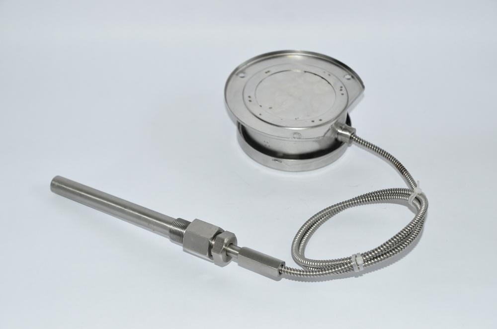
Bimetallic thermometer combines two metals with different linear expansion coefficients, and one end is fixed. When the temperature changes, the thermal expansion of the two metals is different, which drives the pointer to deflect to indicate the temperature. This is bimetallic sheet thermometer, as shown in the figure on the above page. The temperature measurement range is - 80 ~ 500C, which is suitable for temperature measurement when the accuracy requirement is not high in industry. As a temperature sensing element, bimetallic sheet can also be used for automatic temperature control.

Bimetal Thermometer,Marine Bimetal Thermometer,Bimetallic Thermometer For Marine Pipeline,Bimetallic Thermostat Thermometer
Taizhou Jiabo Instrument Technology Co., Ltd. , https://www.taizhoujiabo.com
