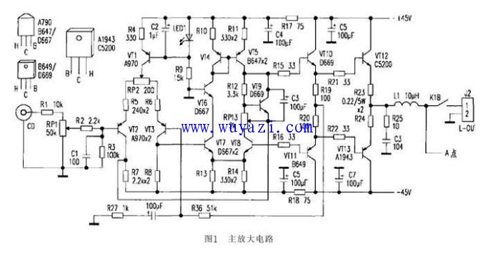
High fidelity 45W discrete component power amplifier production circuit diagram
In today's rapid development of electronic technology, most amplifiers use the design of integrated circuits. For electronic enthusiasts, it is also a basic skill to be able to create a high-fidelity amplifier with separate components. The power amplifier described in this paper adopts a fully-separated component structure. It adopts a two-stage asymmetric structure differential circuit in the input stage and voltage amplification stage. The amplification linearity is good, the frequency response is wide, and the influence on temperature drift and power supply fluctuation is strong, and the sound quality is sweet. Full of charm, it is worth a try.
First, a brief analysis of the circuit principle

Figure 1 shows the main amplifier circuit of the power amplifier. VT2 and VT3 form the input stage differential circuit. VT1, LED1, R4, R9 and C2 form the constant current source circuit of the input stage differential circuit. When the LED1 is normally illuminated, the voltage difference between the positive and negative terminals is constant between 1.8V and 2V, and the noise is less than the Zener diode, which is commonly used in power amplifier circuits. The voltage difference of 1.9V at the positive and negative ends acts on the VT1 emitter junction loop. The VT1 emitter-collector current is constant at (1.9V~0.6V)/680Ω≈1.9mA. In the case where the parameters of the VT2 and VT3 differential input circuits are completely symmetrical, the current flowing through the VT2 and VT3 emitter-sets is half of 1.9 mA, that is, 0.95 mA. RP2 changes the feedback resistance of the VT2 and VT3 emitters, causing positive and negative symmetrical changes in the quiescent operating points of VT2 and VT3, and finally changing the DC potential at the midpoint of the output stage.
The voltage drop on R7 and R8 is 2.2kΩ×0.95mA≈2.1 V under normal conditions, and it is used as the emitter junction bias voltage of the voltage amplification stage VT7 and VT8 differential circuits. The current flowing through the VT7 and VT8 sets is (2.1 V to 0.6 V) / R13 ≈ 4.5 mA. VT4 and VT5 form the mirror current source load of the VT7 and VT8 differential voltage amplification stages. VT6 is connected to a common ground state as a load resistor of VT7.
VT9, R12 and RP3 form the bias circuit of the push stage and output stage, and at the same time play the role of temperature feedback control of the final stage power tube. Adjusting RP3 changes the voltage between the VT9 set-shot, which in turn changes the quiescent bias current of the push and output stages. On the other hand, VT9 and power stage pairs VT12 and VT13 are installed on the same heat sink, which plays a role of feedback control of VT12 and VT13 temperature, preventing the VT12 and VT13 from being too high and causing excessive output current to burn out. The principle of temperature feedback control is that when the output current of VT12 and VT13 increases, the set-shot current of VT9 increases and the collector-shooting voltage decreases when the temperature rise exceeds the standard, thereby reducing the static output current of the push stage and the output stage, and the power pair is The current and temperature of the tubes VT12 and VT13 are controlled within a safe range.
VT10 and VT11 constitute the push stage, and the DC voltage drop on the emitter resistors R19 and R20 is used as the bias voltage of the power output stages VT12 and VT13. The RP3 can be adjusted to change the static output current of VT12 and VT13. R26, C9 and R27 form the AC feedback circuit of this unit, and the voltage amplification factor of the whole machine is 52 times (Av+=1+R26/R2 7=52). The feedback extraction point is selected at the symmetrical midpoint of the push stage, which minimizes the influence of the speaker on the small signal input stage. Compared with the usual method of selecting the feedback point at the output midpoint of the symmetry, the sound quality is improved obviously. The control is strengthened and the transient is better.
Screen Protector Cutting Machine
Tpu Hydrogel Cutting Plotter,Inteligent Screen Protector Cutter,Mobile Phone Cut Plotter,Screen Protector Cutter
Shenzhen TUOLI Electronic Technology Co., Ltd. , https://www.hydrogelprotectors.com
