Introduction of CC1020 Chip Talking about CC1020's working principle and its parameter characteristics
This article mainly introduces the CC1020 chip, and focuses on the working principle and parameter performance of the CC1020 chip.
CC1020cc1020 is an ideal UHF monolithic transceiver chip. It is mainly used in the ism (industrial, scientific research and medical) frequency band and the srd (short range device) in the 426/429/433/868/915mhz frequency band. It can also be used in the frequency range of 402mhz~470mhz and 804mhz~940mhz multi-channel equipment.
cc1020 module features
1. The frequency range is 402mhz-470mhz. 2. High sensitivity (up to -118dbm for 12.5khz channels) 3. Programmable output power, maximum 10dbm 4. Low current consumption (rx:19.9ma) 5. Low voltage power supply (2.3v) Up to 3.6v) 6. The data rate can reach up to 153.3kbaud. 7. The spi interface is equipped with internal registers. 8. The standard dip spacing interface is convenient for embedded applications. 9. The communication distance is long. The 10dbm power condition can transmit about 600 meters outdoors.
cc1020 working parameters
The main operating parameters of cc1020 can be programmed through the serial bus interface, such as output power, frequency and afc. In receiving mode, cc1020 can be regarded as a traditional superheterodyne receiver. The rf input signal is amplified by the low-noise amplifier (lna and lna2), and then flipped through the integrator (i and q) to produce an intermediate frequency if signal. In the intermediate frequency processing stage, the i/q signal is converted into a digital signal by adc after mixed filtering and amplification. Then perform automatic acquisition control, channel filtering, demodulation and binary synchronization processing, output digital demodulation data on the dio pin, and obtain synchronized digital clock data on the dclk pin. rssi is in digital form and can be read out through the channel interface. rssi can also be used as a programmable carrier detection indicator. In the transmission mode, the synthesized rf signal is directly fed to the power amplifier pa. The RF output is the fsk signal, which is generated by the digital bit stream fed to the dio pin through fsk modulation. A high frequency filter can be used to get Gaussian frequency shift keying gfsk. The receiving/sending switch circuit inside the chip makes the antenna easy to access and match.
cc1020 signal transceiver interface
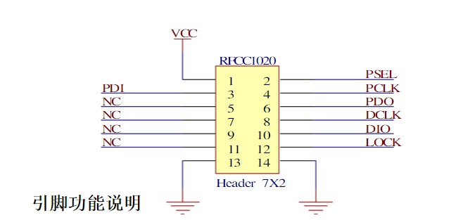
The connection between the cc1020 signal transceiver interface and the microcontroller is shown in Figure 1. The microcontroller uses pins p2.6 and p3.4 to connect with the bidirectional synchronous data interface dio and dclk of the cc1020.
Figure 1 cc1020 and microcontroller connection circuit A bidirectional pin of the microcontroller is connected to the dio of the cc1020 for data transmission and reception (input and output). dclk provides data timing and must be connected to an input of the microcontroller. Data output can choose to use a separate pin. At this time, set the cc1020 interface register sep_di_do=1. In synchronous mode, the lock pin is used as data output, while the dclk pin is used as data output in asynchronous mode, and the dio pin is only used for data input. A pin of the microcontroller can be used to monitor the lock signal of the phase-locked loop, that is, the lock pin signal. When the phase-locked loop is locked, the lock pin is logic low. It can also be used for carrier detection and monitoring other internal test signals. cc1020 can be set into three different data transmission modes: synchronous nrz mode, synchronous Manchester code mode and asynchronous transmission uart mode. These three modes have their own characteristics. Synchronous Manchester code has the best anti-jamming ability, but the baud rate is twice as low. Asynchronous transmission uart is the simplest to implement, but the anti-jamming ability is the worst, while the synchronous nrz has better anti-jamming ability than uart. , But slightly worse than the synchronous Manchester code, the difficulty of realization is also between the two. Considering that the microprocessor basically supports uart serial communication, this mode is selected, and the test result can fully meet the requirements.
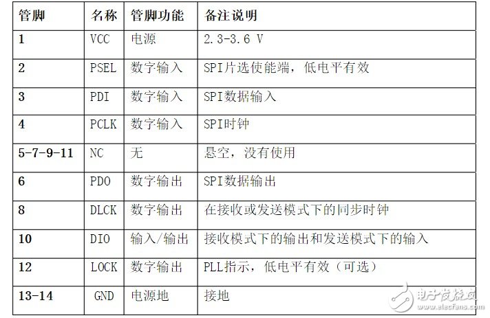
cc1020 pin interface description
Remarks 1. The voltage range of the vcc pin is 2.3-3.6v. It cannot be outside this range. If it exceeds 3.6v, the module will be burned. The recommended voltage is about 3.3v; 2. The single-chip microcomputer with no integrated spi function in the hardware can also control this module, and use an ordinary single-chip io port to simulate spi timing for read and write operations;
cc1020 structure configuration interface
The cc1020 is programmed through a simple four serial spi interface. There are 8-bit structure configuration registers. The address of each register is 7 bits, and 1 bit is used as a read/write bit to initialize the read or write operation. A complete configuration of cc1020 requires sending 33 data frames, each with 16 bits (address 7 bits, r/w 1 bit, data 8 bits). The time required for a complete configuration depends on the frequency of pclk. If the pclk frequency is 10mhz, the time to complete a complete configuration is less than 53ms. Set cc1020 to low power consumption mode, only need to send one frame of data, so the time required is less than 2ms. All registers are readable.


This is the end of the introduction about the CC1020 chip. If there are any deficiencies, please correct me.
Related information recommended: CC1020 Chinese information
Gaming headphones, which are suitable for playing games, have extraordinary sound quality - true, clear, and surrounding feeling makes your pulse accelerate and excited.For game users, a high-performance Gaming Headset allows players to experience the immersive feeling in the game. For the gaming players, the gaming headset should also be able to assist the game player to improve combat effectiveness.
Among so many headsets, gaming headsets have a sensitivity advantage. The relatively closed listening environment is also more conducive to the game player to feel the details of the sound and improve the judgment of the sound. Therefore, compared with the traditional headphones, the gaming headset has the advantage of positioning ability, and can express the sense of direction of the sound, and is more suitable for expressing the sound clearly in the 3D games. Moreover, the game headsets that serve the player generally also enhance the low-frequency sense, thereby promoting the game plot and making it easier for the player to fully devote himself to the game, thereby achieving "listening to the voice and walking through the hundred steps."

Wireless Gaming Headphones,Bluetooth Gaming Headset,Gaming Headset,Wireless Gaming Headset
Shenzhen Linx Technology Co., Ltd. , https://www.linxheadphone.com
