Magnetic pulse therapy device
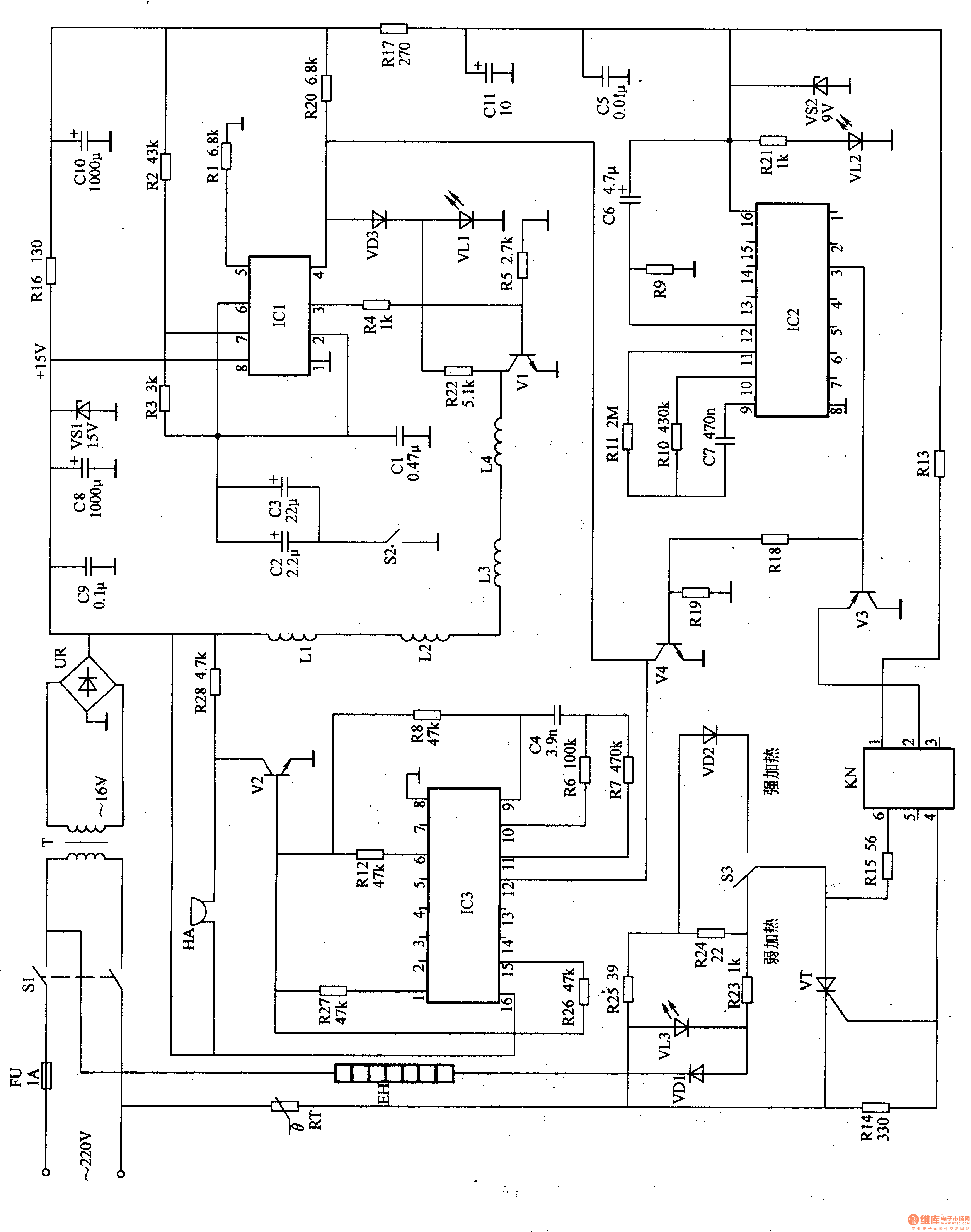
Circuit Operation Principle The magnetic pulse therapy device circuit consists of a power supply circuit, a timing control circuit, an audible cue circuit, an electromagnetic pulse control circuit, and a heating control circuit, as shown in Figure 9-15.

The power supply circuit consists of fuse FU, power switch Sl, power transformer T, rectifier bridge stack UR, filter capacitor C5, C8-C11, current limiting resistor Rl6, R17, anus 1, Zener diode VSl, VS2 and power indicator LED VL2 composition.
The timing control circuit is composed of a timer integrated circuit IC2, resistors R9-R11 and capacitors C6, C7.
The audible cue circuit is composed of resistors R6-R8, R12, R18, Rl9, R26-R28, capacitor C4, transistors V2, V4, timer integrated circuit IC3, and buzzer HA.
The electromagnetic pulse control circuit is composed of a time base integrated circuit lCl, resistors Rl-R5, R2O, R22, a capacitor Cl-C3, a switch S2, a transistor Vl, a diode VD3, a light emitting diode VLl and an electromagnetic coil L1-M.
The heating control circuit is composed of a transistor V3, a solid state relay KN, a thermistor RT, a thyristor VT, resistors R14, Rl5, R23-R25, diodes VD1, VD2, a light emitting diode VL3, a control switch S3, and a heater EH.
Turn on the power switch Sl, AC 220V voltage through T step-down, UR rectification, VSl voltage regulation and C8 filter to generate +l5V voltage, one way to supply electromagnetic pulse control circuit and sound prompt circuit; one way through R16 and R17 current limit buck, After VS2 is regulated to +9V, it is supplied to IC2 and KN.
IC1 and peripheral RC components form a multivibrator whose oscillation frequency is controlled by S2. When S2 is turned on, the oscillation frequency of the multivibrator is 1 Hz; when S2 is turned off, the oscillation frequency of the multivibrator is 5 Hz.
The oscillation pulse signal (lHz or 5OHz) output from the 3 pin of IC1 is applied to the base of V1 via R4, so that V1 is intermittently turned on, and a magnetic pulse is generated on L1-L4.
The timing time of the timing control circuit is set to 6Omin. After the power is turned on, the internal oscillator of IC2 oscillates and starts to divide the frequency. It outputs a low level from the 3 pin of IC2, so that V3, KN and VT are both turned on, and EH is energized. When the timing time is over, IC3's 3 pin goes high, turning V3, KN and VT off, and EH is powered off and stops working. At the same time, V4 is turned on, and the oscillator composed of IC3 and peripheral components oscillates, and high-level pulses of different intervals are output from pins 6 and 15 of IC3, so that V2 is intermittently turned on, and HA emits a prompt sound.
After the EH is energized, the heating starts. As the temperature increases, the resistance of the RT increases. When the temperature reaches a certain temperature, the resistance of the RT increases to near infinity, so that the EH stops heating, but the magnetic pulse control circuit still takes jobs. After the EH stops heating, the resistance of the RT begins to decrease. When the resistance decreases to a certain value, the EH is energized again to start heating. The above process is repeated over and over until the end of the time.
VLl is the working indicator of the magnetic pulse circuit, which flashes with the operating frequency of the multivibrator; VL2 is the power indicator light, which illuminates after the power is turned on; VL3 is the heating indicator, which lights up when the EH is energized and heated. , extinguished when EH stops heating.
Component selection
Rl-Rl5, R18-R22 and R26-R28 all use 1/4W metal film resistors; R16, RI7 and R23-R25 select 1/2W metal film resistors.
RT uses a PTC type positive temperature coefficient thermistor.
Cl, C5, C7 and C9 use monolithic capacitors or CBB capacitors; C2, C3, C6, C8 select aluminum electrolytic capacitors with a withstand voltage of 35V; ClO and Cll select aluminum electrolytic capacitors with a withstand voltage of 25V; C4 Use high frequency ceramic capacitors.
Both VDl and VD2 use IN54M silicon rectifier diodes; VD3 uses 1N4148 silicon switching diodes.
VLl-VL3 selects high brightness LED of φ3mm.
Both VSl and VS2 use lW silicon Zener diodes.
UR selects 3A, lOOV rectifier bridge stack.
V1 selects TIP4lC type silicon NPN Darlington transistor; V2 and V4 select S9013 or S805O type NPN transistor; V3 selects S9012 or 58550 type silicon PNP transistor.
VT uses MAV97A6 type thyristor.
ICl selects NE555 or HAl7555 type time base integrated circuit for use; lC2 and 1C3 select CD4060 or HCF406OBE type timer integrated circuit.
KN selects the MOC3041 solid state relay.
Ll-L4 is made of enamel wire of about φ1mm.
EH uses a far-infrared heating wire, which is wrapped around the heating plate when in use.
HA uses a piezoelectric buzzer.
S1 selects SA, 220V bipolar power switch; S2 selects small single-pole toggle switch; S3 selects 5A, 220V single-pole two-position switch.
T selects lOW, the secondary voltage is 15-18V power transformer.
Pvc Bar Mat,Pvc Bar Spill Mat,Logo Bar Mat,Pvc Barmat
Cixi Mingsheng Rubber & Plastic Co.,Ltd. , https://www.cixidoormats.com