[Photo] 10 cases of acousto-optic integrated circuits
In the colorful and colorful toy world, there have recently emerged many realistic electronic toys with vivid voices, such as dynamic voice-controlled electronic birds, light-controlled electronic frogs, space fantasy echoed spaceships, electronic police cars, and electronic ambulances. , "Big Brother" telephone, toy electronic piano, toy sound and light gun, etc. After the introduction of audio electronic toys, it has won the favor of parents and children. The analog sound integrated circuit is the core device of sound electronic toys. It can emit a variety of analog sounds, such as gongs and drums, pianos, accordions, mandolins and other musical instruments, crickets, frogs, bird calls, running water, wind, down The sound effects of rain, the sound of cars, ships, planes, sirens, guns and various explosions in nature. Analog sound integrated circuits have a high performance-to-price ratio, so they are widely used in many fields such as electronic toys, instruments, security warnings, etc. This article introduces the application examples of analog acoustic integrated circuits.
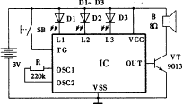
2. Eight-tone electronic small pistol Figure 3 is a circuit schematic of the eight-tone electronic small pistol. IC is a single-key 8-sound analog sound integrated circuit. It can emit rifle sound, laser gun sound, bomb sound 1, bomb sound 2, machine gun sound 1, machine gun sound 2, artillery sound under the control of a trigger switch With 8 kinds of simulated sounds such as the above 7 kinds of sound reverb sounds, each time the trigger switch SB is pressed, a sound is emitted in sequence. SB in Figure 3 is the pistol trigger switch (automatic reset). Each time the trigger is pulled, it is equivalent to the switch SB being closed once. The speaker emits a sound. Continue to pull the trigger, and the speaker generates the above 8 simulated sounds in sequence. The IC can also drive 3 to 5 LEDs to produce optical effects. The sound of this electronic pistol is realistic, and the shape is exquisite and beautiful, so that children can't put it down.
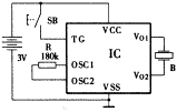
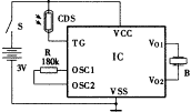
â‘¢ 3. Wallet anti-theft alarm card The ICs in Figures 4 and 5 are integrated circuits that can emit a "wooh ..." alarm analog sound. The trigger switch SB of the circuit shown in FIG. 4 uses two thin phosphor copper sheets with a length of 20 mm and a width of 5 mm, which are bent into an arc shape to make a touch switch. The entire circuit is encapsulated in a plastic clip the size of a business card. Normally the switch SB is separated due to the natural tension of the two copper pieces (equivalent to SB disconnection). When the switch is pressed or touched, the two copper pieces are in contact. Make the IC work and sound the alarm. Figure 5 uses a light-controlled trigger circuit to replace SB with a photoresistor CDS. When the photoresistor CDS encounters weak light, the IC is triggered to work. The circuit shown in Figure 5 is also installed in a plastic clip, and a small light transmission hole with a diameter of 5 mm is opened at the position where the photoresistor is aligned. The two kinds of anti-theft alarm cards specially used for wallets have proved to be effective in practice.
â‘£
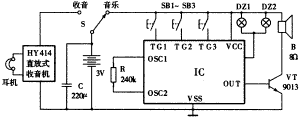
⑤ 4. Pocket radio / music dual-use machine Pocket radio / music dual-use machine, compact in size, easy to carry around, suitable for people to use outdoors. Figure 6 is a schematic diagram of the machine's circuit. For the radio part, the HY414 or TA7642 direct-release monolithic radio special integrated circuit is used. It has high sensitivity, low power consumption, very simple circuit, and easy installation and debugging. The music part adopts a piece of analog sound integrated circuit that generates 3 kinds of disco music. When working, switch S to the "music" block. By selecting SB1 ~ SB3, the IC can output different disco music sounds. At the same time, the IC can also drive the small electric beads DZ1 and DZ2 to flash simultaneously with the music rhythm.
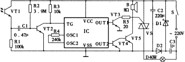
â‘¥ 5. Automatic electronic warning line It is very necessary to set up an electronic warning line in places such as military defense zones, warehouses, dangerous areas and other places where the passage of outsiders is prohibited. 7 is a circuit diagram of an automatic electronic warning line. It is actually a simple light-controlled alarm circuit. When the IC is working, it can control two output signals separately: the composite amplification circuit composed of VT1 and VT2 for one signal amplifies the alarm sound and drives the horn speaker to sound. The other signal is triggered by VT3 to trigger the bidirectional thyristor (or relay) to turn on, illuminate the spotlight D, and display the words "forbidden to pass".
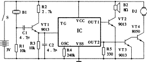
⑦ 6. A lively birdie on the balcony of the voice-activated electronic bird, sings and sings non-stop. When you take a closer look, oh! It turned out to be a plush toy bird. It's strange, how could this toy bird move and bark? The answer lies in the circuit shown in Figure 8. IC is an integrated circuit for simulating bird sounds. Transistor VT1, piezoelectric ceramic buzzer B1, resistors R1, R2 and R3, capacitors C1 and C2, etc. constitute a voice-activated electronic switch. Normally when there is no sound, B1 is in a high-impedance state. When the high-five, whistle or surrounding sound reaches a certain intensity, the piezoelectric ceramic chip generates an induced voltage due to vibration, and the VT1 is triggered by R1, and the VT1 emitter outputs a positive trigger pulse. , The TG terminal of the IC is triggered, and the IC is triggered to work. The audio signal of bird sound is output at OUT1, amplified by VT2, and then the speaker B2 is sounded; the pulse signal at OUT2, amplified by VT3 and VT4, drives the 1.5V DC motor DJ to rotate, and then the model bird is generated by the mechanical transmission device Corresponding action.
⑧ 7. Voice-activated key tag Voice-activated key tag is a practical and interesting new electronic key ring. When you forget where the key (stuck on the voice-activated key card) is, you can slap or blow a few whistle, and the key card immediately emits a clear "di, di, di" sound, as if telling the owner " I am here, I am here ", very interesting. Fig. 9 is a circuit diagram of a voice-activated key card. The analog sound integrated circuit used in the voice control key has a characteristic that is significantly different from the above-mentioned analog sound integrated circuit, that is, its receiver and sounder are the same piezoelectric ceramic buzzer, and the IC's peripheral circuit has only one piezoelectric buzzer B And 1 oscillation resistance R (oscillation resistance can also be built into the integrated circuit). The entire voice-activated key card circuit is extremely simple and very compact.
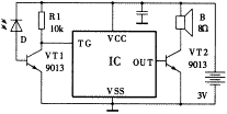
⑨ 8. "Live ammunition" shooting game machine The most notable feature of this game machine is the use of "live ammunition" shooting, with a sense of actual combat and irritating, which is unmatched by traditional electronic target shooting game machines. Fig. 10 is an electrical schematic diagram of a photoelectron bomb. IC is an analog sound integrated circuit that simulates the sound of a machine gun. S is a power switch, which is controlled by the trigger of the model machine gun, and a capacitor C is connected between the trigger terminal TG and the positive power terminal VCC. When S is closed, the small electric ball DZ lights up, and at the same time, the power supply voltage VCC is immediately added to the TG terminal due to the mutation of C. The IC is triggered to work and emits a series of "tap, tap, click" machine gun sounds. Because the capacitance of C is small, it is fully charged in an instant, which is equivalent to the trigger circuit being turned off, so even if S is turned on, the IC does not work. If you need to shoot again, you must put down the “bullet shell†you hit and install a new “bulletâ€. During manufacture, the circuit shown in FIG. 10 is made into a bullet shape, the metal shell of the bullet is the positive pole of the IC power supply, and the bottom of the bullet leads out the negative pole of the power supply and one end of the speaker, respectively. 11 is a circuit diagram of a photoelectric target. IC is a voice integrated circuit. When the photodiode D is fired by the photoelectric gun, VT1 is turned on instantaneously, the IC is triggered by a negative pulse signal, and a "hit" sound is made through the speaker B.
(10)
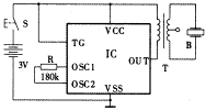
(11) 9. Super Loud Valuables Alarm Figure 12 is a schematic diagram of the circuit applied to a valuables stolen alarm. The circuit is simple, easy to manufacture, and practical. If the manufacturer can develop into a small product and supply it with valuables such as jewelry, it may open up a new way to attract customers. S in Fig. 12 is a switch, which is normally under pressure, and S is in the off state. When the protected item is moved by a person, S is closed and the IC works immediately. The audio output terminal OUT of the circuit is connected to a transformer T (a small transistor radio output transformer can be used, the secondary is connected to the 8Ω speaker to the OUT terminal and VCC terminal of the IC, and the primary is connected to the piezoelectric buzzer B with a sound-assist cavity) , So that the buzzer B emits a loud and rapid alarm sound.
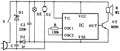
(12) 10. Soundtrack dynamic landscape light painting The production adopts the integrated sound of flowing water and bird song simulation integrated circuit to produce and produce soundtrack dynamic landscape light painting. This modern decorative painting that beautifies the home and returns to nature is very popular with consumers once it comes out. Fig. 13 is an electric schematic diagram of a dynamic landscape lighting hanging picture of a soundtrack. Connected to 220V AC power supply, stepped down by capacitor C, D1, D2 half-wave rectified voltage regulator, capacitor C2 output 3V DC voltage, IC began to work. Since the trigger terminal TG is often connected to the VCC terminal, the speaker B always emits rhythmically sounds of flowing water and the clear and melodious singing of the birds. At the same time, the 220V AC small motor DJ rotates, driving the gear device to make the background picture of clouds and flowing water produce a moving effect. This kind of sound and light dynamic painting that presents a miniature natural landscape that is also true and magical, undoubtedly adds a bright landscape to the modern urban home.
(13) |
Antenk box header connector,Those products are used in more or less every known application within computer-, industrial-, telecommunication and specific automotive markets. This product technology allows cost effective connections between printed circuit boards based on removable or permanent connections based on a longterm proofed way of assembly. box header connectors are available with the traditionally used pitch of 2.54mm and the pitch of 2.00mm,1.27mm.
Antenk Box header/Ejector header Description and Application:
Box header/ ejector header connector, With DIP straight/vertical, SMT,Right angle, 2.54pitch, 2.0pitch, 1.27pitch,
The commonly used Pin ways have 6P,8P,10P,14P,16P,20P, 24P,26P,30P,34P, 40P,50P,64P.
Box header/ ejector header and IDC Flat Cable connectors are two of the most commonly used connectors. Box headers can be found in nearly all electronic equipments.
This is a IDC product which allows cost effective connections between circuit boards based on permanent connection (using transition connector) or removable connection
(Using for IDC flat cable connectors).
Box header
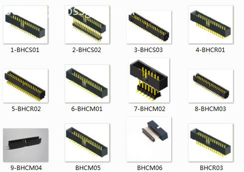
Ejector header

Box Header,Box Header Connectors,Ecu Box Header Connector,Latch Box Header Connector,1.27mm Box Header Connector,2.00mm Box Header Connector,2.54mm Box Header Connector
ShenZhen Antenk Electronics Co,Ltd , https://www.pcbsocket.com


