PLC electrical control cabinet wiring _PLC electrical control cabinet layout and structural design
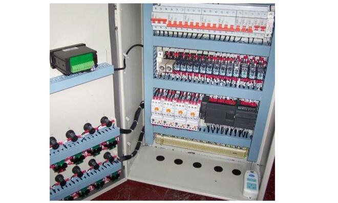
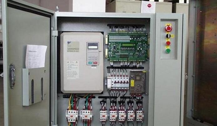
The PLC control cabinet refers to the programmable control cabinet, and the control cabinet refers to the complete control cabinet, which can realize the electrical cabinet controlled by the motor and the switch. The PLC control cabinet has protection functions such as overload, short circuit and phase loss protection.
PLC control cabinet can complete equipment automation and process automation control, achieve perfect network function, stable performance, scalability, strong anti-interference and so on. It is the core and soul of modern industry. PLC control cabinets, frequency conversion cabinets, etc. can be designed according to user requirements to meet user requirements, and can be matched with human-machine interface touch screen for easy operation. The device can be connected with the data transmission of the DCS bus host computer modbus, profibus and other communication protocols; the control and monitoring realized by the industrial computer and Ethernet.

air switch
A total air switch, this is the power control of the entire cabinet. I believe that every cabinet must have something.
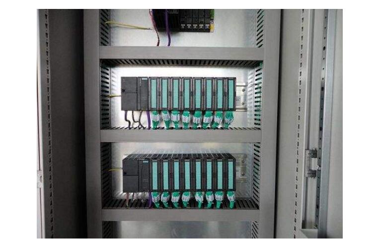
PLC
This should be chosen according to the needs of the project. For example, if the project is small, it can be directly an integrated PLC. However, if the project is relatively large, it may require modules and card-type, and may also require redundancy (that is, two sets of alternate use).
power supply
A 24VDC switching power supply, most PLCs are equipped with a 24VDC power supply, depending on whether you really need to determine whether you want this switching power supply.
Relay
The general PLC can directly send the command to the control loop, but it may also be relayed by the relay first. For example, if the output of your PLC is 24VDC, but the picture drawn in your control loop needs 220VAC for the node, then you must add a relay to the PLC output, that is, the command is issued. The relay acts, but then the node of the control loop is connected to the normally open or normally closed point of the relay. It is also possible to choose whether or not to use the relay depending on the situation.
Terminals
This must be something that is essential for every cabinet, depending on the number of signals that can be configured. If you just need a simple PLC control cabinet, you need these things. If you need other things in your control cabinet, you can see the situation increase. For example, if you are likely to supply power to some on-site instruments or small control boxes, you may have to increase the number of open spaces. Or if you want the PLC to connect to the host computer, you may need to increase the switch. Subject to availability.

Power supply: DC DC 24V, single phase AC 220v, (-10%, +15%), 50HZ
Protection level: IP41 or IP20
Environmental conditions: The ambient temperature is between 0 °C and 55 °C to prevent direct sunlight; the relative humidity of the air should be less than 85% (no condensation). Keep away from strong vibration sources and prevent frequent or continuous vibrations with a vibration frequency of 10-55HZ. Avoid corrosive and flammable gases.
PLC electrical control cabinet wiringThe normal operation of a system production line, electrical plc and slave station is equivalent to the human heart and blood vessels, who can not be separated, but in order to normal heart operation and normal blood flow, then must start from the basics ---- wiring .
Wiring in the PLC-cpu template wiring, the front connector terminal wiring must be pressed nose, can use 0.75 square and 1 square, if the wiring to the front connection line pressure line loose or virtual connection will affect the stability of the entire system.
The power supply is divided into 220V and 24V. The signal line is divided into digital input and output. The signal line and the power line should be pressed in the terminal. It must be locked with a set screw and firmly pulled by hand.
The following is a field example: the site is a small reversible rolling mill, the signal line and power supply from the transmission cabinet to the PLC cabinet and other slave stations are corrected one by one before commissioning, but there is no correction of the template line to the relay in the console. The signal line of the terminal. Normally, the cabinet has a factory debugging record before it is sent from the factory to the site. This line is electrically commissioned. It should not be a problem. It can be in normal operation after the steel has been commissioned. When the console knob switch and tension are good or bad, after the on-site stop, check the DP network and DP communication plugs are no problem, the test console knob is also normal, and then the template light is not illuminated when the knob switch is turned on. Check the connector wiring before the template. When using the hand, the result is more than one loose. Nearly 1 row has 8 wires that are loose. No wonder it will report the fault. After retightening, the steel will be rolled and returned to normal.

Applicable to cabinet type with PLC, usually use fixed cabinet, and the door panel is the whole cabinet type, such as KB cabinet, nine-fold cabinet and 16-fold cabinet, etc. It is not suitable to choose GGD cabinet, fixed partition cabinet and drawer cabinet. Because the components in the PLC cabinet are basically installed on the whole board, if the cabinet type divided by the cabinet door is adopted, it is not easy to install and debug. If the GGD cabinet must be selected, it is necessary to do a non-standard design, the instrument door, the front door and the lower vent door are combined into one whole door, and the front and rear beams are eliminated on the cabinet frame for installation and maintenance.
2, cabinet ventilation system designThe cabinet ventilation scheme adopts the form of air outlet on the front door and the rear door is not added to the air outlet. The air inlet and outlet are respectively equipped with a ventilation filter to prevent dust. The outer dimensions are 320mm×320mm, and the inlet and outlet air area is about 008 square meters. Since the components in the PLC cabinet emit less heat, natural convection can be used. If the wind speed is to be increased, an axial fan can be installed on the outlet filter on the half of the door panel to vent the wind. The top cover of the cabinet has no ventilation holes and is equipped with a non-porous top cover.
3, the choice of line slot specificationsThere are many specifications for the line slot. Commonly used line slots are 25mm, 40mm, 60mm, 80mm, 100mm, and the height is 40mm, 60mm, 80mm, 100mm. The color is preferred.
The principle of selecting the row slot is usually based on the sum of the volume of the line passing through the slot (including the insulating layer) being about 80% of the slot capacity, and the specification of the slot is selected, and the remaining space facilitates heat dissipation of the line. The relationship between the cross-sections can be calculated, that is, the sum of the cross-sections of the wires (including the insulating layer) is about 80% of the cross-section of the wire trough.
Cables larger than 6 square feet are usually not used to manage the wiring harness, but sometimes the layout is neat and tidy. For special cables, such as cable and prefabricated cables of components, they are also placed in the trunking. Special consideration should be given to the assembly design. The cable trough is selected according to the wire diameter and the bending radius, and the cable is placed neatly into the wire trough. As shown in Figure 1.
4, the principle of component layoutThe components in the cabinet are generally arranged from top to bottom and from left to right. It is easy to operate and maintain. The components that are frequently operated or maintained should be installed in a position that is easy to reach. From the height, it should be installed in the height range of 400mm to 1800mm from the ground. If there are many components, consider installing components that are not frequently operated (such as DC power supply) at a height of about 2000mm, and the bottom component installation position should not be lower than 200mm from the ground. Otherwise, the site cannot be wired. Avoid repeating the winding in the line groove during the arrangement, paying attention to cost saving.
4.1 regulated power supply layout
The regulated power supply does not need frequent maintenance, and is a heating device, which is arranged at the uppermost part of the cabinet to facilitate heat dissipation. The wiring is small, the slot is 40mm wide, the slot depth should be considered in the whole cabinet, and the slot with the largest number of wires is unified (the same as the slot depth). The clear distance between the edge of the regulated power supply and the trunking is about 30mm.
4.2 PLC and each unit layout
The unit adjacent to the CPU unit is preferably a unit having less interference such as a special unit and an input unit. For electromagnetic contactors and relays of external circuits, the coils and contacts are sources of interference, so they should be configured separately from the PLC. (roughly above 100mm)
In addition, the module is the main component of the PLC system, which needs to be frequently debugged and maintained, and should be installed in a convenient position. When installing the module, it is arranged from left to right for easy expansion. There are many signal lines, usually 80mm wide slot, the net distance between the upper end of the rack and the slot is about 30mm, and the net distance between the lower end of the rack and the slot is about 80mm.
4.3 Arrangement of circuit breakers
The height of the installation is convenient for operation, and there are no devices that interfere with the operation. Usually 60mm wide slot is used, and the clearance between the upper and lower edges of the circuit breaker and the slot is about 40mm. It is arranged from the left side during installation to facilitate expansion.
4.4 Relay, terminal block layout
The relays and terminal blocks are generally arranged in the front lower part of the cabinet or behind the cabinet. The terminal strips are preferably arranged longitudinally. The inner and outer lines should be separated as much as possible, as shown in Figure 2. Taking into account the wiring habits (left hand line, right hand tool), the trunk on the left side of the general terminal is left to the customer for external line access, and the right line slot is used for internal line management. If the space is tight, you can also share one internal slot or share one external slot for the two columns. Try not to share one slot between the inside and the outside (except for the case of string), otherwise it is inconvenient to manage. The width of the slot is reasonably selected according to the number of relays and terminals. For the external line, since the incoming line in the field generally contains a spare core, a shield layer, etc., the wire diameter is relatively thick, and the outer wire trough should be selected as large as possible.
4.5 Switch and fiber optic box layout
The switch and the fiber optic box are generally arranged in the lower part of the cabinet. The reserved wiring space should fully consider the bending radius of the network cable and the optical fiber, and make it as large as possible to facilitate the access of the field network cable and the optical fiber.
4.6 cabinet lighting
The top of the cabinet is equipped with lighting, which is controlled by a door control switch. One set is arranged on one side, and two sets are arranged on both sides. The light is on when the door is opened, and the light is off when the door is closed.
4.7 Grounding System
4.7.1 Grounding busbar
In the PLC system, all control cabinets equipped with PLC equipment should be equipped with PE protective grounding busbar and TE anti-interference grounding busbar. The PE protective grounding busbar is used to connect the PE grounding point of equipment such as racks and power supplies, and is directly connected to the cabinet. The TE anti-interference grounding busbar is insulated from the cabinet for shielding grounding of the external signal cable.
4.7.2 Cabinet grounding
The structural components such as the mounting plate of the component and the frame of the cabinet should be reliably fixed. The connector used should be padded with a claw-type spring pad, and the yellow-green wire should be led to the PE row from the bottom of the mounting plate. The grounding of the rotating parts of the cabinet should be connected to the cabinet frame using a copper braid.
4.7.3 Grounding the Rack
There are grounding bolts on the rack dedicated to the PE and the rack is attached to the PE busbar. The minimum cross-section of the PE busbar wire is 2mm2.
5, cabinet layout and structural designAccording to the above arrangement principle, combined with the schematic diagram and the list of the cabinets, draw the layout diagram inside the cabinet. Whether it is cabinets, components or trunking, etc., the maximum size must be used, drawn in a ratio of 1:1. After the layout drawing is completed, the structural design of the mounting plate is carried out according to the position and installation method of the components. The material of the mounting plate is usually aluminum-zinc plated, and the thickness is 2.0 mm to 3.0 mm.
Our solar module has high reliability. Minimized micro-cracks with innovative non-destructive cutting technology. Ensured PID resistance through cell process and module material control.

Bifacial Double Glass Module,Silicon Solar Module,Silicon Mono Solar Module,Monocrystalline Silicon Solar Module
Jiangxi Huayang New Energy Co.,Ltd , https://www.huayangenergy.com
