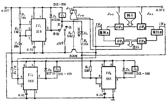
Quantitative injector circuit schematic

The circuit is shown in the figure, where IC1 is a timed square wave oscillator, IC2 and IC3 are both used as hysteresis comparators, and DF1-DF4 is a normally closed electromagnetic threshold to control the flow of liquid. A and B are two dosing cylinders, and the liquid level is measured by the probes INA and INB, respectively.
Relay J1 controls the liquid electromagnetic thresholds DF1 and DF2, and relays J2 and J3 control the quantitative liquid input electromagnetic thresholds DF3 and DF4, respectively.
Silver Zinc Battery For Aircraft
Ag Zn Battery,Ag-Zn Battery For Aircraft,Ag-Zn 45Ah Battery,Silver Zinc Battery For Aircraft
Henan Xintaihang Power Source Co.,Ltd , https://www.taihangbattery.com
