[Technical Article] Sub-low frequency timeline alignment in large PA systems
Usually, the operating frequency band of the PA system is divided into different frequency bands, which are separately replayed by different speakers (the subwoofer is responsible for the low frequency part, and the hoisted speaker is responsible for the medium and high frequency). In other words, that is, the location of the sound source is different, so there will be beneficial or harmful acoustic interference in the frequency band near the crossover point. In the frequency band near the crossover point, it is necessary to adjust the time of arrival of the sound to achieve alignment of the time line.
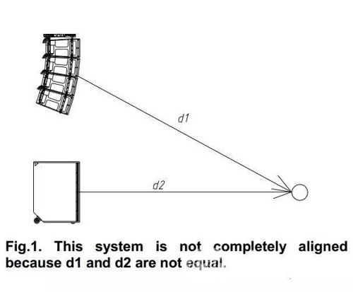
In general, we need to determine the amount of delay based on the difference in distance between the two sets of speakers, but this is not always the case. The phase of the crossover frequency band is affected by the filter, so the application of the delay amount is not always determined solely by distance.
This article briefly describes how to achieve correct timeline alignment under this system architecture. First, we will look at the situation of smaller systems in the soundless room; then apply the timeline alignment process to large PA systems and perform measurement verification on the system.
measuring equipment
A soundless room with walls, ceilings and floors filled with sound absorbers allows us to make some "clean" measurements and record the phase response of the system. The volume of the non-sounding chamber is 400 m3, and the reverberation time in the frequency band above 200 Hz is <0.2 s.
We need a measurement system based on the Fast Fourier Transform (FFT) design to obtain the amplitude and phase response. We chose some small speakers as sound sources that will be used to simulate a small speaker system for large PA systems.
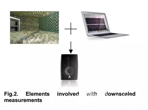
Miniaturization systems allow us to understand how a real system performs in real-world applications. Measurements of miniaturized systems can never replace measurements made in real-world applications, but can help us provide a lot of information before the final system setup in a real-world environment. These knowledge gained in the laboratory will greatly assist us in our daily work in the real environment.
Measurement process
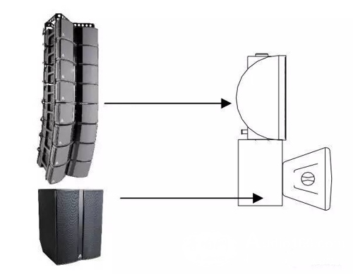
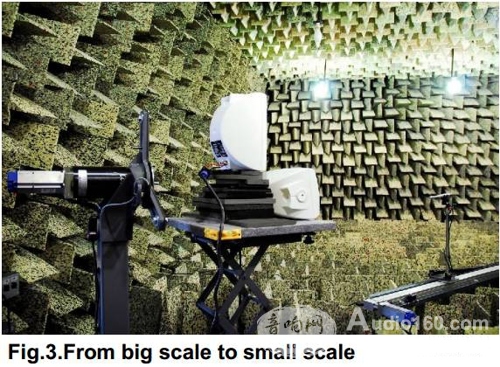
First we will build a small system consisting of 2 small speakers. The first speaker is used to simulate the subwoofer (using an external crossover device to limit its operating frequency band) and place it on the base plane of the measurement platform. The second speaker will be used to simulate the mid-high frequency speaker and placed above the first speaker, in addition to the slight difference in the physical location of the two speakers. In this way, the two speakers are in a timeline unaligned state, like a large PA system containing a hoisting mid-range woofer and a ground-stacked subwoofer.
By measuring this miniaturized system and using delay correction, we can avoid the interference that occurs when two speakers simultaneously play the same source signal.
What happens when there are overlapping parts of the working frequency bands of the two sources?
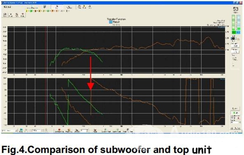
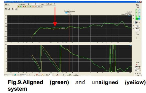
The measurement results of the first speaker (secondary low frequency) and the second speaker (medium high frequency) are displayed in the same window. When we compare the phase and amplitude curves of the two speakers, we find that there is a phase difference in the portion where the two speakers work in the overlapping band (200 – 300 Hz).
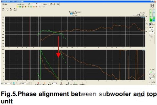
By increasing or decreasing the delay of the subwoofer, the phase curves of the two speakers in the overlapping portion of the operating band (200 – 300 Hz) coincide.
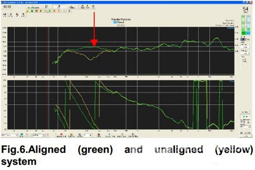
Finally, we compare the unaligned curve with the aligned curve, and the time-line aligned corrected frequency response curve is flatter.
What happens when the crossover frequencies of the two sources are the same?
We again measured the aforementioned speaker system and compared the phase and amplitude curves of the two sources to find a phase difference at the crossover point (270 Hz).
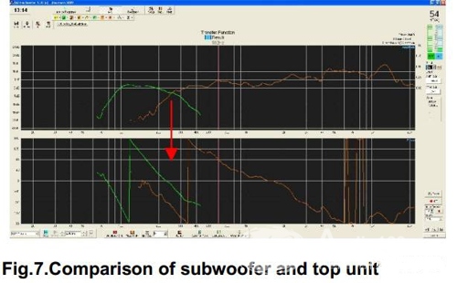
The delay is increased or decreased in the sub-low frequency feed signal chain so that the phase curves of the two sound sources at the crossover point (270 Hz) overlap.

In this example, the improvement is not as obvious as in the previous example. But in both examples, the time-aligned system has better response characteristics.
Field measurement
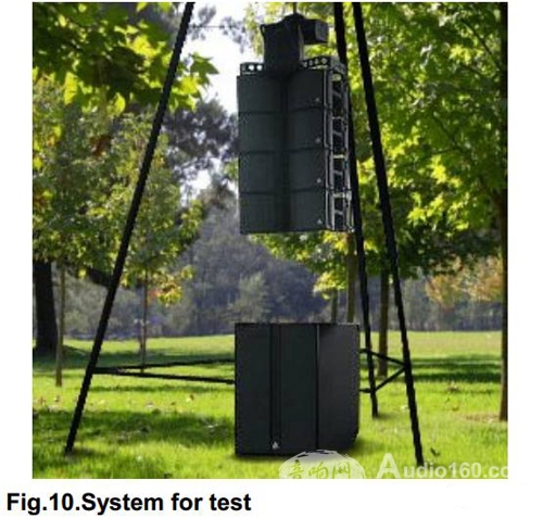
The field measurement system consists of an array of 4 speakers, with a subwoofer placed underneath the main speaker array.
The initial measurements of the system are saved and phase corrected based on the observations (and the same method used in the laboratory). The calibration results are very obvious. When the system's timeline is aligned, we get a very flat frequency response curve.
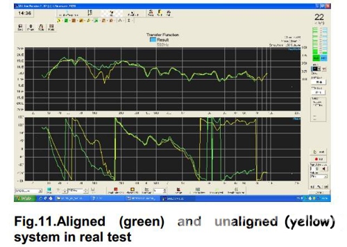
The results of field measurements are somewhat different from those measured in small systems in the laboratory. Some irregular phase response curves appear in the field measurements due to the lack of coherence at certain frequencies.
in conclusion
Proper timeline alignment for PA systems like linear array speaker systems is important for system performance optimization. When used with subwoofers, phase shifts can cause significant adverse effects in the crossover region. Small systems are measured in a non-sounding room to predict the behavioral characteristics of the system prior to field measurements. The best way to align sub-low frequency timelines is to use a phase measurement tool. The system response characteristics of the phase deviation corrected will be significantly improved.
Author: Natà lia Milan & Joan Amate
Compilation: Yi Ke International Jin Lei
Our company specializes in the production and sales of all kinds of terminals, copper terminals, nose wire ears, cold pressed terminals, copper joints, but also according to customer requirements for customization and production, our raw materials are produced and sold by ourselves, we have their own raw materials processing plant, high purity T2 copper, quality and quantity, come to me to order it!
Cable Terminals
Taixing Longyi Terminals Co.,Ltd. , https://www.lycopperterminals.com
