The basic concept of the queue! From the queue to the realization of the serial buffer
The concept of queue
Before that, let’s review the basic concept of queues: Queue: It is a first-in-first-out (First In First Out, referred to as FIFO) linear table, which only allows insertion at one end (entry into the queue), and at the other end Delete (dequeue).
Characteristics of queue
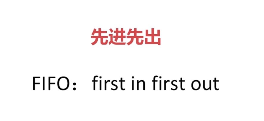

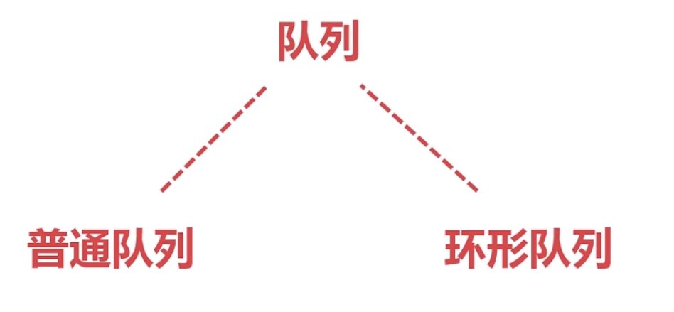
Two common forms of queues
Normal queue
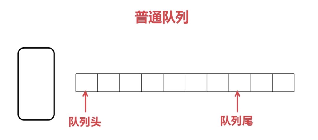
In a computer, every information is stored in a storage unit. For an analogy, the small square grids in the above figure are storage units. You can understand it as a common array that stores our information one by one.
When there is a large amount of data, we can't store all the data, so when the computer processes the data, it can only process the first one. Then after the processing is completed, the data will be released before processing the next one. Then, the memory of the processed data will be wasted. Because later data can only be queued backward, if you want to move the remaining data forward once, then the efficiency will be low, which is certainly not realistic, so the circular queue appears.
Circular queue
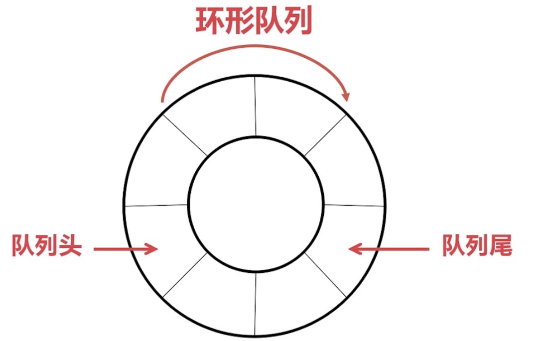
Its queue is a ring. It avoids the shortcomings of ordinary queues, but it is a bit difficult to understand. In fact, it is a queue. It has a queue head and a queue tail, and it is also a first-in first-out (FIFO). We use a clockwise way to sort the queue.
Head: The end that allows deletion is called the head of the queue. Tail: The end that allows insertion is called the tail.
The realization of circular queue: In the computer, there is no circular memory, but we have processed the sequential memory, so that a certain segment of memory forms a ring, so that they are connected end to end. In short, this is actually an array, only However, there are two pointers, one to the head of the queue and one to the end of the queue. The pointer to the head of the queue (Head) is the data that can be read in the buffer, and the pointer to the end of the queue (Tail) is the data that can be written in the buffer. You can move the two pointers (Head) & (Tail) to the buffer The data is read and written until the buffer is full (the end is connected), the data is processed, the data can be released, and new data can be stored.
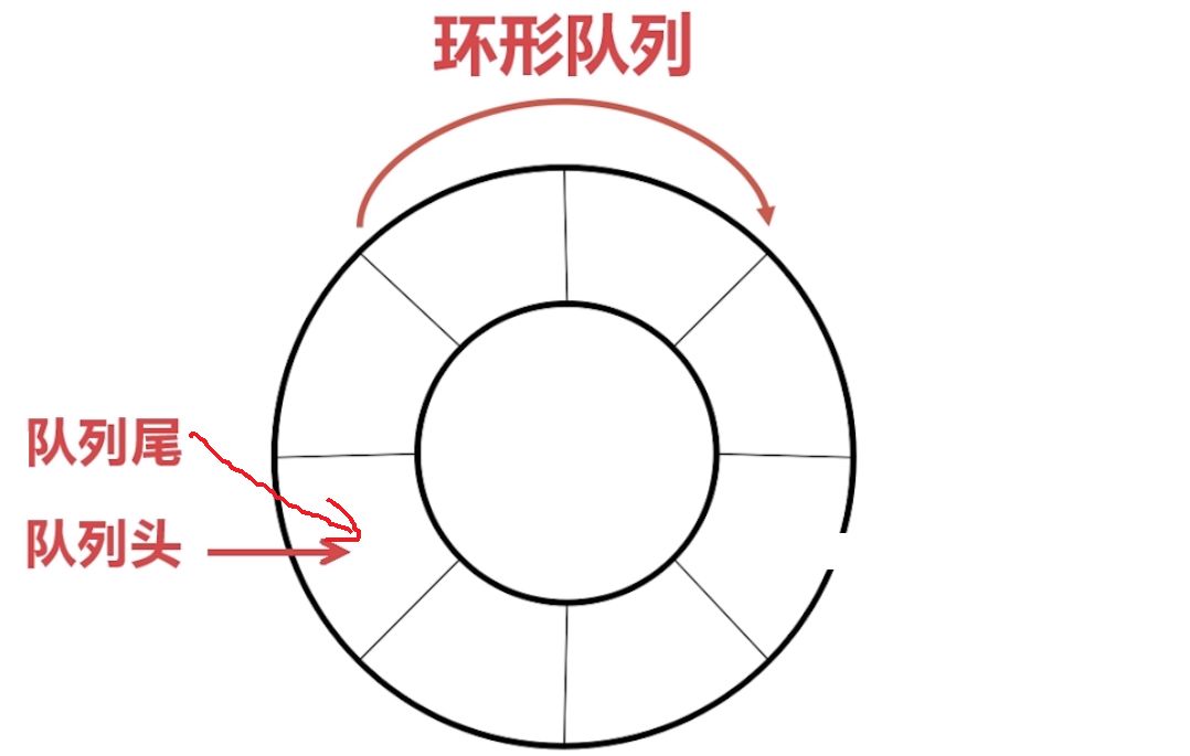
Principle of realization: When initializing, the head and tail of the queue point to 0. When there is data storage, the data is stored in the address space of '0', and the end of the queue points to the next place where data can be stored. When the data comes, store the data to the address "1", and then the end of the queue points to the next address "2". When the data needs to be processed, the data in the '0' space must be processed first, that is, the data in the head of the queue. After the data is processed, the data in the '0' address space is released, and the head of the queue points to the next one that can process the data. Address 1'. So as to realize the data reading and writing of the entire ring buffer.
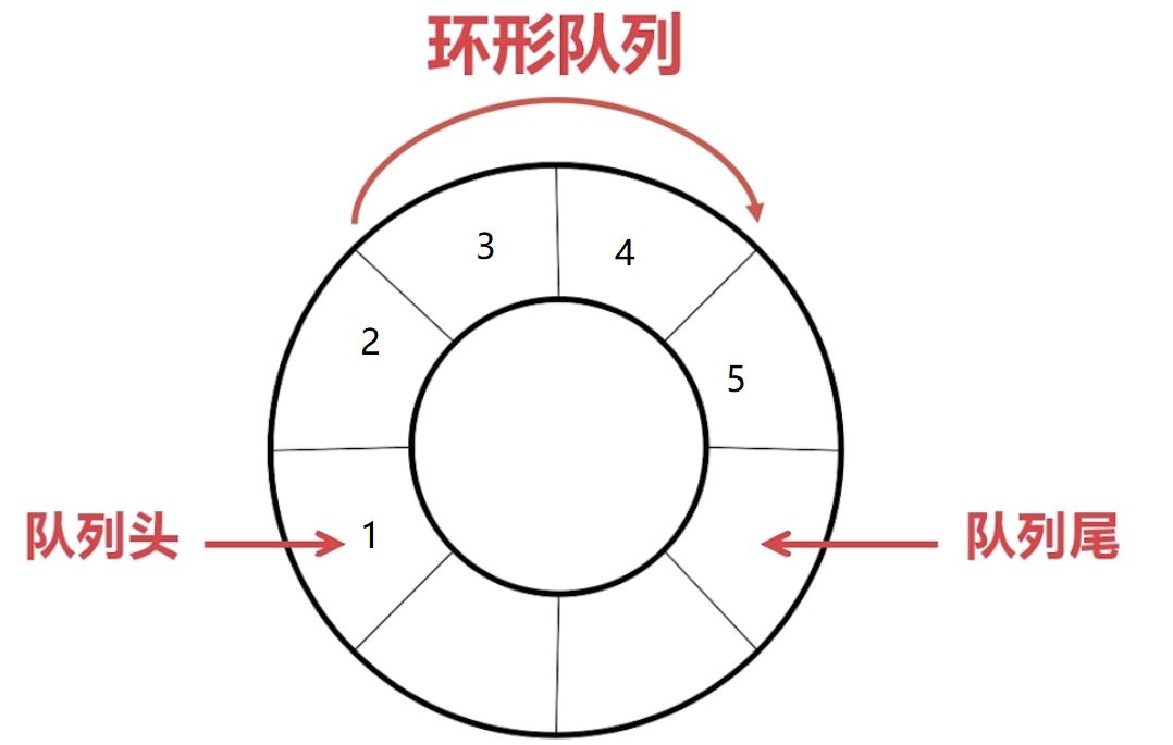
Looking at the picture, the head of the queue points to the stored data, and this data is to be processed. The data processed by the next CPU is 1; and the end of the queue points to an address where data can be written. When 1 is processed, 1 will be released. And point the head of the queue to 2. When a data 6 is written, the pointer at the end of the queue will point to the next address that can be written.
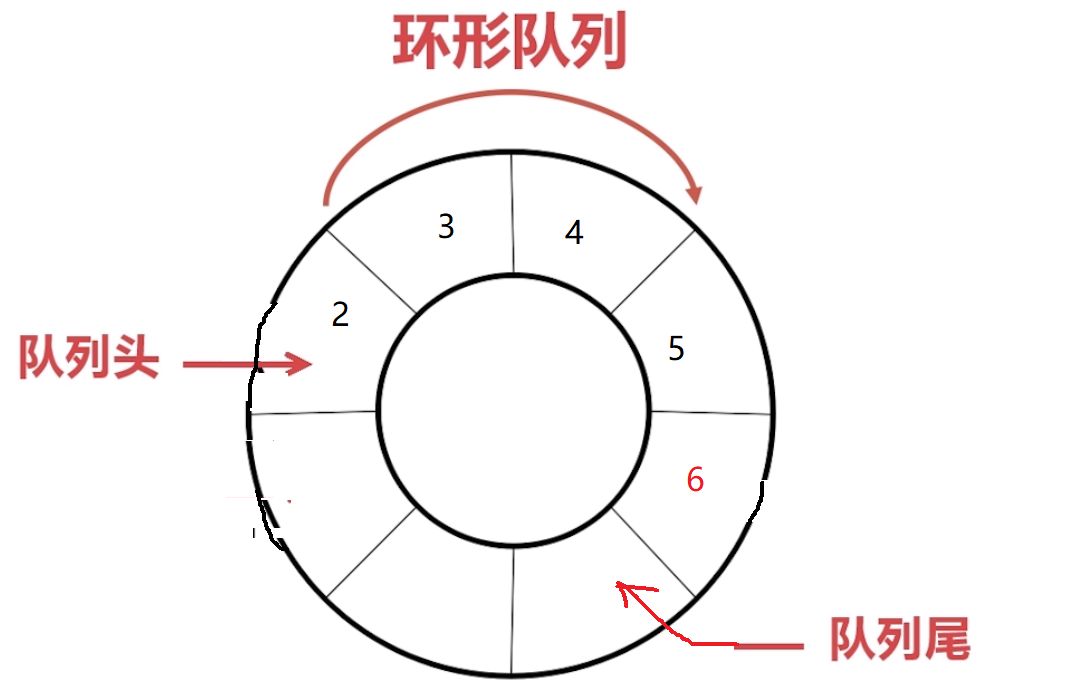
If you understand the circular queue, follow the song to implement it step by step with code:
Realization from queue to serial buffer
Serial port ring buffer transceiver: In many entry-level tutorials, we know that the serial port transceiver is: receive a data, trigger an interrupt, and then send the data back. This processing method is not buffered. When the amount is too large, or when the data is received too fast, we have no time to process the received data. Then, when the data is received again, the previous data will be returned. Unprocessed data is overwritten. Then there will be packet loss, which is a fatal wound to our program.
So how to avoid this from happening? Obviously, some of the queue characteristics mentioned above can easily help us achieve what we need. Cache the received data, so that the processing speed is slightly buffered, so that the processing speed can catch up with the receiving speed. The advantages and disadvantages of ordinary queues and circular queues have been analyzed above, so we must use circular queues to achieve this. . The following is the implementation of the code:
â‘ Define a structure:
1typedef struct2{3 u16 Head; 4 u16 Tail;5 u16 Lenght;6 u8 Ring_Buff[RINGBUFF_LEN];7}RingBuff_t;8RingBuff_t ringBuff;//Create a ringBuff buffer
â‘¡Initialize structure related information: make our ring buffer connected end to end, and there is no data in it, that is, an empty queue.
1/** 2* @brief RingBuff_Init 3* @param void 4* @return void 5* @author æ°æ°6* @date 2018 7* @version v1.0 8* @note Initialize the ring buffer 9*/10 void RingBuff_Init (void)11{12 //Initialize related information 13 ringBuff.Head = 0;14 ringBuff.Tail = 0;15 ringBuff.Lenght = 0;16}
The initialization effect is as follows:
The code to write to the ring buffer:
1/** 2* @brief Write_RingBuff 3* @param u8 data 4* @return FLASE: the ring buffer is full and the write failed; TRUE: the write succeeded 5* @author æ°æ°6* @date 2018 7* @ version v1.0 8* @note Write u8 type data to the ring buffer 9*/10u8 Write_RingBuff(u8 data)11{12 if(ringBuff.Lenght >= RINGBUFF_LEN) // Determine whether the buffer is full 13 {14 return FLASE;15 }16 ringBuff.Ring_Buff[ringBuff.Tail]=data;17// ringBuff.Tail++;18 ringBuff.Tail = (ringBuff.Tail+1)%RINGBUFF_LEN;//Prevent illegal access beyond the border 19 ringBuff.Lenght++; 20 return TRUE;21}
Code implementation for reading the data in the buffer:
1/** 2* @brief Read_RingBuff 3* @param u8 *rData, used to save the read data 4* @return FLASE: there is no data in the ring buffer, reading failed; TRUE: read successfully 5* @author Jie Jie 6* @date 2018 7* @version v1.0 8* @note Read a u8 type data from the ring buffer 9*/10u8 Read_RingBuff(u8 *rData)11{12 if(ringBuff.Lenght == 0) //Judgment is not empty 13 {14 return FLASE;15 }16 *rData = ringBuff.Ring_Buff[ringBuff.Head];//First-in, first-out FIFO, 17 from the buffer head // ringBuff.Head++;18 ringBuff.Head = (ringBuff.Head+1)%RINGBUFF_LEN;//Prevent illegal access beyond the border 19 ringBuff.Lenght--;20 return TRUE;21) 
There are two things to pay attention to for read and write operations:
1: Determine whether the queue is empty or full. If it is empty, it is not allowed to read data, and return FLASE. If it is full, it is not allowed to write data to avoid overwriting existing data. Then, if the processing speed cannot keep up with the receiving speed, the size of the buffer can be appropriately increased to exchange space for time.
2: Prevent illegal access of the pointer beyond the boundary, the program has instructions, and the user needs to grasp the size of the entire buffer.

Then in the serial port receiving function:
1void USART1_IRQHandler(void) 2{3 if(USART_GetITStatus(USART1, USART_IT_RXNE) != RESET) //Receive interrupt 4 {5 USART_ClearITPendingBit(USART1,USART_IT_RXNE); //Clear flag bit 6 Write_RingBuff(USART_ReceiveData(USART1)) Read the received data 7 }8} 
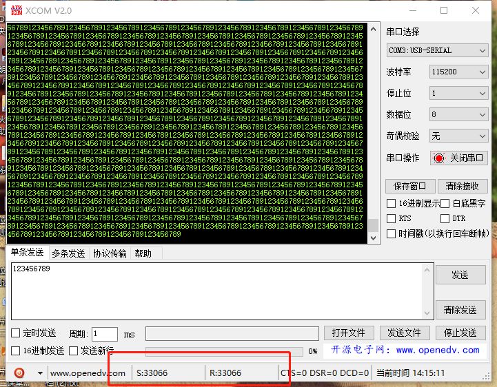
No packet loss occurred in the test data.
supplement
For the current stage, Jiejie, I write code myself and gradually learn to regulate. All the code snippets are very readable, and also very portable. I used the macro definition to decide whether to open the ring buffer to send and receive data. The code transplanted to everyone will not have other side effects, just open the macro definition to use it.
1#define USER_RINGBUFF 1 //Use the ring buffer to receive data 2#if USER_RINGBUFF 3/**If you use the ring buffer to receive serial data***/ 4#define RINGBUFF_LEN 200 //Define the maximum number of received bytes 200 5# define FLASE 1 6#define TRUE 0 7void RingBuff_Init(void); 8u8 Write_RingBuff(u8 data); 9u8 Read_RingBuff(u8 *rData);10#endif
Of course, we can use idle interrupt and DMA transmission, which is more efficient, but some single-chip microcomputers do not have idle interrupt and DMA, so the role of this kind of ring buffer is great, and transplantation is easy. At the same time, you can also refer to the following Gokit3.0 STM32 source code analysis to understand this mechanism better.
GALOCE Various products of Portable Truck Axle Scale, also called Mobile Vehicle Weighing Scales, providing product images and basic parameters with each Portable Axle Weigh Scales and Wireless Portable Axle Scale; We are a professional Chinese manufacturer of Portable Truck Axle Scale, and look forward to your cooperation!
Portable Truck Scale,Portable Axle Scales,Portable Vehicle Weighing Scales,Mobile Vehicle Weighing Scales
GALOCE (XI'AN) M&C TECHNOLOGY CO., LTD. , https://www.galoce-meas.com
