Simple light control switch circuit diagram (video assembly and demonstration + detailed circuit schematic diagram)
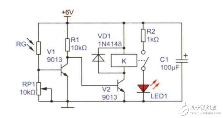
The light control switch circuit consists of relays, LEDs, freewheeling diodes, potentiometers, capacitor resistors, battery boxes, etc.
The circuit is a typical dark switch, that is, when the external light is dark, the relay K pulls in, drives the load to work, and lights up LED1. When the light is bright during the day, the photoresistor RG is low resistance, V1 is turned on, its collector outputs low level, and the base of V2 connected to it is also low level, so V2 is cut off, relay K does not work, LED1 is at Off state. When the light is dark at night, RG is high resistance, V1 is cut off, its collector outputs high level, the base of V2 is also high level, V2 is turned on, K pulls in, LED1 is lighted up, thus achieving Dark pass operation. Changing the resistance of RP1 can adjust the sensitivity, that is, when the light is dark to what extent the relay will act. When the resistance of RP1 is reduced, the base voltage of V1 will also decrease, so the light control sensitivity will be reduced, and darker light is required So that the relay K can be closed. Conversely, when the resistance of RP1 increases, the base voltage of V1 increases, and the sensitivity of the light control will increase. VD1 is a freewheeling diode, which protects V2 when the relay K is disconnected.
Adjusting the resistance of the potentiometer RP1 can control the sensitivity of the light. If you block the brightness of the light with your hand, the relay will act and the LED will light up; if the resistance of RP1 is reduced, the sensitivity of the photosensitive can be reduced. Use a darker paper tube to block the light. , The LED will light up.

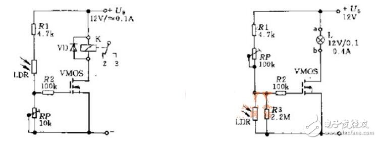
The power MOS field effect transistor can be used as a power switch, and the sensitive element of the switch can be a photoresistor LDR. When light shines on the photoresistor, the LDR has a low resistance value, and a signal is added to the gate of the field effect transistor, source and drain The relay coil K changes state from the surface, and generates a control action or sends a signal. If the photoresistor LDR is connected to a low potential, no light will shine on the photoresistor in the dark, and the resistance of the photoresistor is the same.
As shown in the schematic diagram of the light control switch circuit

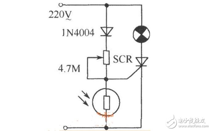
As shown in the figure is a simple light-controlled switch. In some public places, such as corridors, street lights, etc., install automatic light-controlled switches, which is not only convenient but also energy-saving. It will automatically turn on the light when it is dark, and automatically turn off when it is dawn. Adjusting the 4.7MΩ potentiometer can be applied to different types of photoresistors and light up under certain conditions (darkness).

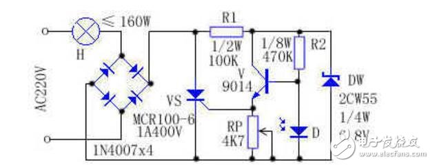
Light-controlled electronic switch, its "on" and "off" are realized by the conduction and blocking of the thyristor, and the conduction and blocking of the thyristor is the brightness of natural light (or artificial brightness) Controlled by the size. The device is suitable as a street, dormitory corridor or other public place lighting, which can control the lighting of day and night to save electricity.

Working principle: The circuit is shown in the above figure. After 220V AC power passes through the bulb H and the rectifier full bridge, it becomes a DC pulsating voltage, which acts as a forward bias and is applied to the thyristor VS and R branch. In the daytime, when the brightness is greater than a certain level, the photodiode D presents a bottom resistance state ≤ 1KΩ, so that the transistor V is cut off, its emitter has no current output, and the unidirectional thyristor VS is blocked due to no trigger current. At this time, the current flowing through the bulb H is ≤2.2mA, and the bulb H cannot emit light. Resistor R1 and Zener diode DW make the V bias voltage of the triode not exceed 6.8V, which protects the triode. At night, when the brightness is less than a certain level, the photodiode D presents a high resistance state ≥100KΩ, so that the transistor V is turned on, the emitter has a voltage of about 0.8V, the thyristor VS is triggered to turn on, and the bulb H emits light. RP is a brightness selection element that realizes switching in the early morning or evening.
Installation and debugging: During installation, put the soldered printed circuit board into a transparent plastic box and fix it, connect it in series with the controlled electric light H, and make it face the sky curtain or the brighter space in front of the house lighting window , Avoid direct illumination of night lights within 3 meters. Debugging should be carried out in the evening, adjust the size of the RP resistance, so that the controlled electric lamp H starts to light up under proper brightness.
As the Distribuidor of Snowplus, we can provide you with Snowplus pods, Snowplus kits, disposable Snowplus 100% original supply, wholesalers, reasonable prices
It only takes 7-15 days from China to the destination, and there are both flavors and colors in stock.
The latest date, price concessions, if you are interested welcome to ask me
Snowplus Vape,Snowplus Disposable Vape,Snowplus Vape Kit,Snowplus Vape Pod,Snowplus Pods
TSVAPE Wholesale/OEM/ODM , https://www.tsvaping.com
