Aside from the concept of electromagnetic field theory
The author of this article, Feng Wutian, is an old blogger of "Electronic Engineering Album". He hopes to use his own learning to achieve his own career and hope to benefit others. I shared a lot of my own experience in entrepreneurship and management. The blog post "Understanding Electromagnetic Field Theory" has been published since the publication of 109 readers who liked this article, reading 6844, commenting 56, which is very popular among readers. The blogger also interacts with the netizens in the comments. The following is the blog post content:
From junior high school to even smaller, we have come into contact with the circuit, comparing the voltage to the height of the water source, the current ratio to the water flow, and the resistance that characterizes the voltage and current is the size of the water pipe. From junior high school to college graduation (excluding specialized electromagnetic fields, and deep understanding), we have always understood this. Because the concept of circuit, voltage, current, and resistance comes from the waterway, water pressure, water flow and water resistance seen in reality, it is very intuitive and image, and it feels no problem for a long time, so it is very popular. The dilemma of circuit theory The first problem encountered in circuit theory is that two closely following signal lines will interfere with each other. This introduces a better explanation of the magnetic field theory: the presence of alternating currents excites alternating magnetic field changes. Some magnetic lines of force surround each other's signal lines. According to Ampere's law, mutual inductance interacts with each other. This magnetic field theory can be said to be a perfect explanation. Of course, the two signal lines that are close to each other are not only affected by the magnetic field, but also the electric field, which depends on the proportional relationship between voltage and current. The second problem encountered in circuit theory is that when the wires of a loop are irregular and messy, the signal source signal cannot be perfectly transmitted to the terminal, high-frequency distortion, and signal integrity is impaired, which limits high-speed signal transmission. And this, the circuit theory can not explain, the magnetic field theory can not explain, need a third theory. Circuit theory encountered a third problem, unable to explain the antenna? How to break a section of a wire that is not connected can radiate energy out, and the circuit theory must have a loop, which is completely incomprehensible. Circuit theory cannot explain the fourth problem: transmission line impedance, a coaxial line, nominally 50 ohms. What is the physical quantity? Where is this 50 ohm? The carrier of a signal is the transmission of a signal in energy hardware, characterized by voltage or current, but regardless of voltage or current, it is based on energy.
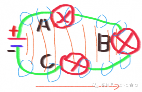
In reality, the transmission of energy is from A to B. In the microscopic world, there are only two kinds of energy transfer, that is, based on particle transfer, like stone throwing, or based on wave transfer, like sound or water wave, only These two. However, the circuit is based on a circuit. Everyone thinks that the current is left from the positive pole of the power supply to the negative pole of the power supply, or the electrons flow out from the negative pole to the positive pole. This is often mentioned in the circuit theory, which is deeply rooted in the hearts of the people, but this obviously exists. The problem is that inside this loop, in the end, the load is powered first? Is it near the positive A or C near the negative?

We know that electrons have mass, and the speed of moving in metal is very slow, far less than the speed of light, but the establishment of electricity is the speed of light, so the basis of circuit establishment is obviously not the initial condition of electron movement, which can be compared with the speed of light. There is only an electromagnetic field, which is a wave that can transfer energy and also meet energy transfer conditions. Field structure model Since the theoretical basis of the circuit is the electromagnetic field, the energy transfer must be from the source point to the terminal. It is impossible to form the loop. Then, as shown in the figure below, the red thin line is the electric field, extending from the signal source to the load B, and the blue thin circle It is a magnetic field that also extends from the source to the load B. In theory, the order of the circuits is A, C, B, in this order.
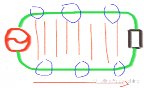
We simplify the above diagram for the transmission line type mode. It can be clearly seen that the electromagnetic field composed of the red and blue magnetic fields is from the signal source to the load resistance. During the propagation process, both the electric field and the magnetic field are present outside the wire, and these electric and magnetic fields are energy fields, so it is clear that the energy is outside the wire and not inside the wire. This is critical. ,
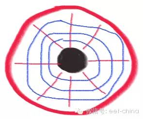
According to the characteristics of energy existing outside the wire, we use it to get different things. For example, in order to achieve transmission, it is necessary to reduce the loss and reduce the external radiation and design a coaxial line. As shown in Figure 1 (cross-sectional view), the plastic between the outer copper and the inner copper wire is filled with a plastic to form a cavity, and the electric and magnetic fields are Distributed inside, the electric field is a red line with two poles in the radial direction, and the magnetic field is a tangential blue line around the copper core. There is no electric field and magnetic field outside the same axis, so there is no external radiation and the loss is the smallest, which is most suitable for electromagnetic field communication.
The signal connection on the PCB can not use the coaxial line, so a coaxial-like solution is designed, called the microstrip line, as shown in Figure 2. It can be seen that the electric field is mostly constrained between the signal line and the reference ground, but the magnetic field is outside, so the microstrip line is suitable for short-distance transmission and is often only suitable for PCB. If the electric field and the magnetic field are exposed to the space as much as possible in order to transmit a signal, such as an antenna, then the two poles need to be separated, as shown in Figure 3.
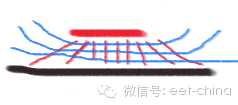
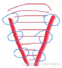
It should be noted that a suspended metal, because the internal resistance is 0, the electromagnetic field can not pass through to form a mirror-like reflection effect, the satellite antenna uses a separate metal plate similar to the shape of the lid as the reflection surface of the satellite signal, using the concave lens principle.
3.5.3 Transmission line impedance The electromagnetic field is a wave, then it must be equal to the electric field energy and the magnetic field energy. Only two energys are equal, and each can be acquainted with each other, and each other is yin and yang. For example, men and women, progeny and reproduction are endless. Then the electric field energy is equal to the magnetic field energy, and the mutual conversion can pass on itself. Note that the equality here is that the energy at the same time is equal. This is completely different from the LC oscillation. Although the oscillation is also the electric field and the magnetic field conversion, it is not at the same time, but the electric field is converted into a magnetic field at this moment. The next moment, the magnetic field is converted into an electric field. , so the total energy does not change, and the conversion between the two can not be passed on. For the electromagnetic field wave, it is the same moment, mutual conversion, electric conversion to magnetic, magnetic conversion to electricity, and energy from the source end is transmitted to the terminal.
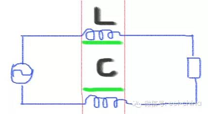
3.5.3 Transmission line differential model
Take a small transmission line, the middle part of the red line, we use a concentrated component to describe, the length of the wire is the inductance L, and the capacitance between the wires is C. The inductance corresponds to the magnetic field, and the capacitance corresponds to the electric field. The two energies are equal. 1/2 * C * U * U = 1/2 * L * I * I can be obtained: Z = U / I = SQR(L/C), SQR is the square root number.

The physical meaning of the transmission line impedance: in the process of electromagnetic field transmission, the electric field and the magnetic field energy are equal, then the voltage and current across the transmission line must satisfy this proportional relationship.
3.5.4 Impedance matching It is easy to understand through the above. Different transmission lines have different impedances. The electromagnetic field is an energy field. If this energy cannot be completely absorbed by the latter stage, it will be reflected back because the energy cannot disappear. . Therefore, the resistance of the terminal is required to be the same as the impedance of the transmission line, so that the transmitted energy can be completely absorbed without causing reflection to cause signal blur. The reason why ordinary lines cannot transmit high frequencies is because of various reflections that cause the signals to be blurred and distorted. In general, both the signal source and the terminal are required to match the impedance of the transmission line, so that even if the terminal reflects the signal, it can be absorbed by the resistance of the source. When some transmission lines are particularly short, far less than the signal wavelength, the impedance may not need to be considered too much, because the transmission line is too short, even if the reflection is folded many times, the signal will not be too harsh, so it is not necessary to consider too much. Our ordinary circuit loop, at low frequencies, is much smaller than the signal wavelength. Even if it is folded many times, it has no effect on the signal. This is why the ordinary circuit does not need to consider the electromagnetic field too much, and the circuit theory can be considered as the electromagnetic field theory at low frequencies. An approximate model When multiple transmission lines or terminals with different impedances are connected together, it is necessary to consider the impedance matching problem between them. It is necessary to introduce a capacitive inductance to achieve impedance matching. This is the RF matching problem that everyone often hears. The RF staff is very energetic in adjusting the signal matching. It is important to pay attention to the fact that, in theory, the transmission line impedance is frequency-independent, because the impedance of the differential line equivalent capacitor inductance of the transmission line changes synchronously with the frequency, which is offset, but the capacitance inductance is introduced to adjust the matching. Different frequencies have different impedances, so there are some frequency response characteristics that are no longer independent of the frequency of the signal. Therefore, when matching adjustments, it is generally adjusted in the desired frequency band. 3.5.5 Long-distance transmission of microstrip line electromagnetic field, generally using coaxial line, because the coaxial line energy can not radiate to the outside, but for the signal line design of the PCB, the coaxial line cannot be used, so based on the electromagnetic field theory, the micro is designed. With a line.

3.5.5.0 microstrip line cross-sectional model
As shown in the model diagram on the right side of the figure above, the signal line with a width of W is above, and the copper of the PCB is generally 0.018 mm. The following is the reference ground, the reference ground should be as large as three times the W width. The height between the signal line and the ground is h, which is generally the standard material FR4 of the PCB. It should be noted that the dielectric constant of FR4 of different manufacturers is basically the same, the data is strictly required by the manufacturer, and it is also related to the frequency, generally 1GHz. Within, the value is 4.2. The microstrip line impedance generally does not need to be calculated by a formula. There are many software tools on the network, and only need to substitute these parameters. The well-known professional software is polar si8000, search for "microstrip line impedance", there are many free online.
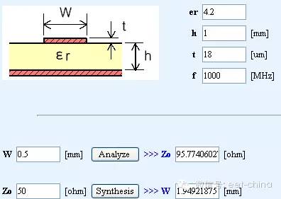
3.5.5.1 Microstrip line calculation interface
In high-speed design, especially long-distance design, as far as possible in the concept of microstrip line design, the closer to the ideal, the better the signal integrity.
Transparent Led Film Screen P6
Good effect: using non-linear point-by-point correction technology, the text is clearer and the sense of hierarchy is stronger; strong reliability: using distributed scanning technology and modular design technology, higher reliability and stability; diverse display modes: supporting multiple Various display modes; easy to operate: the edited contents of the computer are sent to the system control card, and the edited contents can be displayed, and the system operation is very convenient.
Transparent Led Film Screen P6,Flexible Led Display Screen,Indoor Led Display Screen,Transparent Indoor Led Screen Display
Guangdong Rayee Optoelectronic Technology Co.,Ltd. , https://www.rayeeled.com
