Brief Introduction to Design and Performance Impact of Electronic Tag Antenna Based on Hilbert Fractal Structure
The basic system of radio frequency identification (RFID) consists of two parts: the reader and the electronic tag. The RFID system is classified into a passive RFID system, a semi-passive RFID system, and an active RFID system according to different power supply modes when the electronic tag works. The electronic tag of a passive RFID system is called a passive electronic tag. The current typical structure consists of a tag chip, a tag antenna and a tag substrate. The application of passive electronic tags is often attached to the surface of the item to be identified, even embedded in the interior of the item to be identified or in the packaging layer. In order to meet the diversity requirements of application requirements, the miniaturization design and deformation design of passive electronic tags are the main aspects of electronic tag design. The shape of the passive electronic tag is mainly determined by the shape of the tag antenna, so the design of the tag antenna largely determines the performance of the tag chip.
The precondition for the operation of the passive electronic tag is that the energy of the tag chip must exceed the minimum threshold power Pmin of the chip operation, which is also called the sensitivity of the passive electronic tag. Therefore, in order to improve the effective reading distance of the passive electronic tag under the given field strength of the reader, the design of the tag antenna should be as close as possible to the best match of the impedance of the tag antenna in the working frequency band to achieve the tag. The antenna transmits the maximum power to the tag chip in the reader field. Literature [1] made a comprehensive summary of such technology. The basic idea of ​​the tag antenna design is to change the impedance curve of the antenna and match the impedance curve of the tag chip. The specific implementation method can be attributed to various loading techniques of the antenna. Typical loading methods include: loading with lumped elements; loading with dielectric materials; loading with short-circuit technology; loading with the surrounding environment of the antenna; loading with antenna bending or aperture variation. In fact, the basic idea of ​​the loading technique for changing the antenna structure and the fractal antenna is the same, and the design idea of ​​the fractal antenna is derived from the development of fractal geometry or fractal theory.
The fractal theory was proposed by Manderblot in 1975. The structure of the fractal structure generally has proportional self-similar characteristics and space filling characteristics. In the antenna design, the size reduction and wide-band characteristics of the tag antenna can be realized by utilizing the characteristics of the ratio self-similarity and space filling of the fractal structure.
Based on the above ideas, this paper designs an electronic tag antenna based on Hilbert fractal structure, and studies the influence of the relative dielectric constant and thickness of the tag antenna substrate on the performance of the tag antenna.
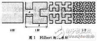
2 Hilbert fractal iteration principleThe Hilbert fractal has loose self-similarity: the 0-order Hilbert is a square-shaped "half-ring" structure with a side length of b, and the first order is to fill each edge with a 0-order structure, thus on each side. A "half-ring" structure is formed, and its side length is a, and a/6 is called a proportional coefficient of the Hilbert fractal, as shown in FIG.

It can be seen from Fig. 1 that the contour area of ​​the 1, 2, 3, ..., n-order Hilbert fractal is exactly the same as that of the 0th order, that is, the contour area of ​​the Hilbert fractal remains unchanged regardless of the number of iterations, and there are always only 2 endpoints.
As an analysis, the total length of the n-th order Hilber fractal can be calculated by the following formula (1). For example, when n is 0, 1, 2, 3, they are: 3b, 5b, 9b, 17b.
Vinoy et al. discussed in detail in the literature [2,3] that the Hilbert curve was found in the design of compact resonant antennas. The performance of the Hilbert fractal antenna is reduced to λ/10, but the performance is similar to the λ/2 dipole. In the literature [4], Zhu studied the influence of the feed point position on the input impedance of the Hilbert fractal antenna. It is found that the radiation resistance of the center feed is small regardless of the number of iterations, but the eccentric feed can be properly selected. 50 Ω matching impedance.
3 Study on the influence of dielectric constant and thickness of antenna substrate on antenna performanceIn practical applications of electronic tags, electronic tags are generally sealed. The size and shape of the antenna, the dielectric constant and thickness of the etched substrate material and the peripheral package material all have a non-negligible effect on the performance of the antenna. Therefore, in the design of electronic tags, the influence of the above factors must be considered.

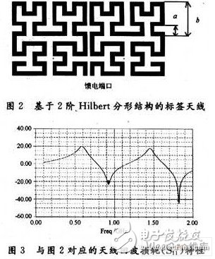
Figure 2 shows a design example of a 2nd order Hilbert fractal antenna. The scale factor a/b=4/11, the size of the antenna is 50 mm & TImes; 24 mm, and the line width is 1 mm. The layout is distributed according to a symmetric dipole. The parameters of the tag chip used in the tag, at 915 MHz, the external impedance of the chip is ZL=18.1-j149 Ω. Without considering the influence of the dielectric plate, the simulation results are shown in Figure 3.
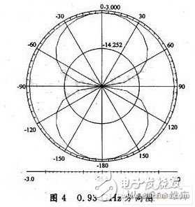
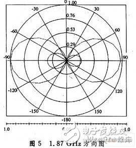
As can be seen from Figure 3, the antenna resonance is at two frequencies of 0.93 GHz and 1.87 GHz. The pattern characteristics (E-plane) of the antenna are analyzed at two resonance points, respectively, and the results as shown in Figs. 4 and 5 can be obtained.

It can be seen from Fig. 4 that at the first resonance frequency, the antenna pattern and the dipole are substantially the same, with omnidirectional radiation characteristics; at the second resonance frequency, the antenna pattern is 90. The twist of °. Consider the antenna size of the first resonant frequency: the length of the antenna is 100 mm, and the length is about 160 mm if a common dipole is used. It can be seen that the antenna size based on the Hilbert fractal structure is reduced by 37.5%.

220V To 110V Transformer,220 To 110 Converter,220 To 110 Voltage Converter,110V Transformer
zhejiang ttn electric co.,ltd , https://www.ttnpower.com
