Depth analysis of four-channel signal source technology
The signal generator is an indispensable electronic instrument in various fields such as scientific experiments and industrial production. At present, the commonly used signal generation technologies include: analog-based electronics, phase-locked frequency synthesis, direct frequency synthesis, and direct digital frequency synthesis (DDS). And so on. In recent years, with the advancement of science and technology, signal generation technology has also achieved sufficient development, and it has developed to high frequency, high resolution, high stability, and multi-channel, etc., based on DDS signal generation technology, with high A series of advantages such as resolution, high stability, and the ability to realize multi-waveform, multi-channel, and output frequency output from extremely low frequency to high frequency (above 200 MHz) are the development direction of signal generation technology. The United States ADI company as the representative of research and development, production of AD9XXX series DDS chip, has been widely used in various types of signal generators and other fields. This article describes in detail the development of a four-channel signal source composed of AD9959DDS chip, which is newly introduced by Analog Devices, USA. Each channel of the signal source can independently output a wideband sine wave signal of 1 Hz to 200 MHz. The output amplitude range is 1 mVpp to 4 Vpp, harmonic distortion is less than or equal to 5%, and the phases between the channels are independently adjustable.
1 Introduction to the AD9959 chipThe AD9959 DDS chip is a direct digital frequency synthesizer chip with four channels and an internal clock frequency of up to 500 MHz that Analog Devices has introduced in recent years. 56-pin LFCSP package, 1.8 V supply, low power consumption. Can directly output up to 200 MHz analog sine wave signal, each channel amplitude and phase are independently adjustable.
The main features of AD9959 are as follows:
(1) 4 independent DDS channels, each channel can independently control frequency, phase and amplitude;
(2) Linear sweep and modulation function with frequency, phase and amplitude;
(3) 32-bit frequency control register;
(4) 14-bit phase shift control register;
(5) 10-bit amplitude output control register;
(6) High speed serial I/O port.
The AD9959 has 16 levels of frequency, phase, or amplitude modulation controlled by external pin input data. Supports frequency, phase or amplitude linear sweep and modulation, widely used in radar and other equipment.
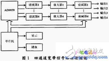
2 The composition of four-channel wideband signal sourceThe four-channel wideband signal source is mainly composed of AD9959 chips and peripheral circuits, differential amplifiers, low-pass filters, wideband amplifiers, numerical control attenuators, and single-chip control circuits, as shown in FIG.

2.1 AD9959 chip peripheral circuit
AD9959 chip 17 pin (DAC_RSET) external resistor Rset, one end of the ground, the resistor is used to control the chip DAC output current range, the current IOUT generally take 8 ~ 10 mA or so.
Rset=18.91/IOUT (1)
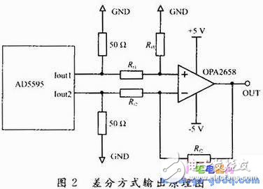
The AD9959 chip has 2 outputs per channel. That is, IOUT and IOUT are open-source current output methods, and each output must be connected with a 50Ω pull-up resistor to complete the current → voltage conversion.
2.2 Difference Amplifier
The output of each channel in the AD9959 chip is a differential mode output (CH_IOUT sum). For practical applications, the single-ended output mode can be used for simplicity, and the CH_IOUT pin is usually used. The waveform quality is acceptable at full-scale output, but waveform distortion is greater at small amplitude output. This is due to the large amount of spurious frequency interference inside the DDS chip. The better solution is to use differential output, which can effectively cancel the interference that is usually in phase at the output.

The differential mode output uses a wideband differential transformer but is limited by the bandwidth of the differential transformer itself. For example, the wideband transformer of the Mini Company can only reach a lower frequency limit of 0.3 MHz (-3 dB). To solve this problem, an active differential amplifier is used, as shown in Figure 2. Using a current negative feedback wideband op amp OPA2658, the -3 dB bandwidth is 800 MHz. The circuit is in the form of a basic differential amplifier. The in-phase and inverting input impedances are 50 Ω. If Rt1=Rt2 and Rf1=Rf2, then the transfer function is:
Usc=UOUT-(-UOUT)=2UOUT (2)
Since the output of each channel of the AD9959 is a complementary form, the output active components are superimposed by the differential amplifier, and the in-phase interference components cancel each other out, so that the waveform distortion is improved.
2.3 Low-pass filter
DDS chip internal direct digital synthesis waveform, the output includes a spurious frequency interference, including the clock frequency, usually at the output (in this case, the differential amplifier output) set the low-pass filter to effectively filter out the interference.
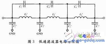
Elliptic function filters have both zeros and poles on a finite frequency. The pole zero produces an equi-ripple in the passband and the limited transmission zero in the stopband reduces the transition zone, making it possible to obtain extremely steep attenuation characteristics
According to the related literature, an elliptic function low-pass filter that satisfies the following requirements is designed with a normalized graph. The filter is required to have a cut-off frequency of 200 MHz, an input and output impedance of 50 Ω, and an in-band maximum ripple of less than 0.25 dB. The minimum attenuation is 60 dB at 264 MHz. The design steps are as follows:
(1) Normalize the known conditions and calculate the steepness coefficient As of the low-pass filter.
As=fs/fc=264/200=1.32 (3)
(2) The literature shows that when Ï is 20% (0.18 dB ripple), a filter with n=7 order is needed. Select a filter with Ωs no greater than 2 and Amin with 60 dB or greater.
The circuit corresponding to θ=50° is selected here because the circuit Ωs=1.305 and Amin=62.3 dB meets the design requirements. The filter circuit is shown in Figure 3, and its normalized component values ​​refer to related literature.

(3) Denormalize the filter with Z = 50 Ω and a frequency scaling factor of FSF (2fc), 1.256 & TImes;10.
2.4 Broadband Amplifiers and Digitally Controlled Attenuators
Because the DDS chip output signal amplitude is small, only 0.3 Vpp after the differential amplifier, in many practical applications can not meet the demand, set up a two-stage broadband amplifier, the magnification is set to 13 ~ 16 times, making the signal source The maximum output can reach 4 Vpp or more. The amplifier uses Texas Instruments' broadband current negative feedback op amp THS3022 with a slew rate of 9 000 V/μs and a 3 dB bandwidth of 2 GHz.
In practical applications, signals with amplitudes as low as a few millivolts are sometimes required, and therefore a five-digit numerically controlled attenuator is provided. The attenuator uses a T-type attenuation circuit consisting of a high-frequency non-inductive resistor with a step of 2 dB and a maximum attenuation of 62 dB. Combining the internal amplitude adjustment of the AD9959 chip, a wide range and high-precision output of the signal source amplitude can be realized.
2.5 MCU control circuit
AD9959 chip I / O control voltage is 3.3 V, the choice of C8051F020 type microcontroller, the microcontroller work fast, strong anti-interference ability, and the use of 8051 core, instructions with the most popular 8051 series microcontroller compatible.
The SCM control circuit arranges a 4&Times;5 keyboard, 128&Times;64 liquid crystal dot matrix display on the hardware setting. A rotary knob is also provided for quick adjustment of frequency or amplitude and is extremely easy to use.
Stainless Steel Pneumatic Mixer
Air Driven Mixers,Air Motor Mixer,Air Operated Mixer,Stainless Steel Pneumatic Mixer
RUDONG HONGXIN MACHINERY CO.,LTD , https://www.rdhxmfr.com
