Design and Verification of Flight Control Software Based on PowerPC
Wang Minghui, Zhu Guangyu, Wang Huimin, Zhang Lihua, China Academy of Air-to-Air Missile Research
Keywords: flight control software; PowerPC; BSP; integrated development tools
With the rapid development of modern information technology, digitization and informatization have become prominent features of high-tech weapons and equipment, and have been widely used in missile-borne systems. The missile loading software usually uses the interrupt-driven, periodic scheduling operation mechanism to control different task slices to execute in different scheduling cycles according to the urgency of the task. This design scheme has simple hardware design and clear software timing. However, in recent years, with the increase in the performance requirements of missile systems, the complexity of missile-loaded software has greatly increased, and higher demands have been placed on the calculation efficiency and accuracy of missile-borne computers. Therefore, software and hardware design and development were developed for high-performance PowerPC computers. Mainly for the PowerPC hardware environment BSP (Board Support Package) and application design and development and validation. The design of flight control software applications is mainly the design and implementation of software timing and architecture, the establishment of verification environments, and software verification. The control algorithm reuses the mature design, thus ensuring the research and verification of key technologies within a short development cycle.
1 BSP design and verification
After the flight control computer adopts PowerPC, the supporting operating system is the VxWorks real-time operating system. In order to enable the VxWorks real-time operating system to run normally on the hardware system with PowerPC as the core, BSP software must be written. The Tornado 2.2 integrated development environment is used by the BSP software to generate the bootrom program and the VxWorks operating system kernel. The system first runs the bootrom program, initializes the hardware resources on the computer board, and then downloads the VxWorks operating system kernel through the serial port (also via the network port). After the VxWorks operating system is running normally on the hardware system, the operating system migration is completed.
1.1 BSP Design
WindRiver's VxWorks real-time operating system has corresponding hardware products and corresponding BSP board-level support packages for different CPUs. The PowerPC used for the flight control computer also has a corresponding ADS board. The biggest differences between the flight control computer board and the ADS board hardware are structural differences. The ADS board is a board for verifying the function of the chip, so all the interfaces of the ADS board implement corresponding functions. The flight control computer board is a board that is customized according to need. The external interface used is only 60Xbus, serial port and interrupt.
When the system develops the BSP, the BSP file of the CPU of the ADS board is used as a template to create the BSP directory bspname of the user in the tornadoarget\config directory, and the file under the tornadoarget\config\all and the BSP template file are copied to the directory. Create a project, modify the relevant source files, and select the appropriate Vxworks mirror type for your situation. Among them, the file under config\all is a public execution module that can be modified independently by the user of the target system. The BSP template file is a module related to the target system. The following uses the design of this system as an example to introduce the BSP software configuration process.
The BSP design of this system is based on the BSP design of the ADS board, and the design is changed. The following changes are mainly designed:
(1) makefile file design: the definition of flash base address and storage space size, according to the size of the SDRAM and the mapped base address to set the RAM address;
(2) Config.h file design: It mainly includes the corresponding functional components required by the computer and shielded unnecessary functional components;
(3) romInit.s file design: initialize the system's memory, close the interrupt, close MMU (Memory Management Units) and CACHE operations;
(4) Bootlnit.c file design: It is mainly to complete the bootrom work. The code that is fixed in flash is moved to SDRAM for execution. Finally jump to the usrinit() function of bootConfig.c.
(5) bootConfig.c file design: complete bootrom image initialization and control. Including the interrupt vector settings, system hardware initialization, configure the operating system kernel, open the CACHE function, call (usr rRoot) root task, initialize the memory pool and system clock, the IO file system initialization and serial driver installation, initialize the WDB agent Create a bootcmdloop task and initialize bootline parameters, download the operating system image file to internal RAM and run the operating system;
(6) usrConfig.c file design: complete the VxWorks image initialization code. Including the interrupt vector settings, system hardware initialization, configuration operation kernel, CACHE function, call (usr rRoot) root task, initialize memory pool and system clock, IO file system initialization and serial port driver installation, initialization WDB agent, Call the upper application;
(7) sysSefia1.c file design: for all serial port settings and initialization.
1.2 Verification of the correctness of the BSP design
The verification of the correctness of BSP migration is mainly verified from the aspects of function and reliability:
(1) SDRAM detection: It is detected using the self-test program under the codewarrior IDE environment. The detection method is to write a batch of regular data into SDRAM, and then read out to compare the data is correct;
(2) Serial port detection: After serial port initialization, observe whether the serial port used for debugging can open the host-side virtual window and whether it can print related information. Finally, the command is used to control whether to download the operating system mapping. If you can complete the above function, the debug serial port is normal. The other two SCC (serial port for communication between the flight control computer and other components) tests are performed after the operating system is up and running, and a large amount of data is sent and received between the host and the host.
(3) Flash detection: After the flash space is configured, the flash can be erased and programmed through the plug-in under the codewarrior IDE. At the same time, flash can be checked using the programmed program under the codewarrior IDE.
(4) Interrupt detection: Use the device to provide PowerPC with a specific frequency interrupt source. After the interrupt is enabled, use the system clock delay function TaskDelay(int ticks) to test the number of all interrupts received within a period of time to determine whether the interrupt is implemented correctly. ;
(5) External interface detection: The device sends data to the PowerPC fixed address space. The PowerPC sends data to the device to detect the correctness of the external interface address mapping.
(6) Reliability test: The stability and reliability of the operating system were verified through repeated power-on tests, aging tests, high-low temperature tests, and vibration tests.
2 Application Design and Implementation
After the BSP design is completed, the bootrom boot is completed successfully. After the VxWorks real-time operating system is running, the application program can be loaded to complete the system control algorithm.
2.1 Interrupt processing
Interruption has always been the core of embedded real-time systems. Some interrupts occur periodically, and some interrupts occur randomly. General requirements for interrupt service routines are as follows:
(1) The longest branching time of the processing flow cannot exceed the interruption time interval;
(2) The interruption processing time is as short as possible;
(3) Try not to operate the interface.
The original software of the flight control computer was driven by the interrupt. All the work was performed in different interrupt services. In order to adapt to the VxWorks constraints on interrupt service routines, the software was specifically designed to normalize interrupts. The transaction handled by the original interrupt service routine is executed in the task corresponding to the interrupt. Only the semaphore is given in the interrupt service, and the corresponding task is interrupted until the semaphore is rerun. Therefore, the respective semaphores are set up for different interrupts, which are used to bind each interrupt and its corresponding task, respectively, to synchronize them. Because the interrupt service processing is extremely simple, even if the software does not use interrupt nesting, it can meet the system's high real-time requirements (the original system, because the acquisition cycle is short, and the basic processing cycle task execution time is long, must be in the basic processing Interrupts are interrupted in the cyclic interrupt service routine, interrupting nested response acquisitions.
2.2 Division of tasks and determination of priorities
The number and division of tasks in real-time systems are issues that need to be carefully considered in the top-level design of system software. In order to ensure that the flight control software has the same timing as the previous flight control software, the maximum degree of inheritance is achieved. That is, the tasks are divided and interrupted to be divided into four tasks: the basic periodic task task_I, the data acquisition task_C, the random task task_K, and the serial SCIA reception. Task_scia task.
Different priorities are set according to the characteristics of the task. task_I() has the lowest priority 103, and other priorities are low to high task_scia(): priority 102; task_K: priority 101; task_C: priority 100.
2.3 Inter-task Communication
VxWorks provides a rich and flexible task-to-task communication mechanism for coordinating the behavior between tasks and interrupts, including shared memory, semaphores, message queues, pipes, socket words, and remote procedure calls. Different communication methods have different characteristics. Compared with complex task management systems, flight control software has fewer tasks and simple communications. In order to maximize the succession of existing scientific research achievements, the communication between tasks adopts the same method as the original: shared memory, ie, the parameters are passed in the form of global variables. Of course, the use of global variables must be very careful. Note that unless used as a synchronization variable, you should not change the value of a global variable between different tasks, that is, you should avoid multiplexing of variables.
2.4 Application Design
In addition to the interruption of the model and task scheduling of the application program, the other algorithm modules are multiplexed and mature algorithm designs.
(1) Interrupt model design
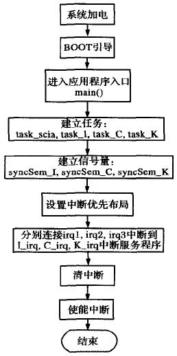
After determining the architecture of the application to use the interrupt binding task, it is necessary to create tasks and semaphores in the application entry function main function, and assign corresponding priorities. Then the interrupt is initialized, the connection is interrupted to the corresponding interrupt service routine, all interrupts are enabled, and then the interrupt can be responded. Figure 1 shows the flight control software interrupt processing model flow.

Figure 1 flight control software interrupt processing model process
When an external interrupt arrives, the program jumps to the interrupt service routine to execute, the interrupt counter is incremented, and then the semaphore is released. The task bound to the interrupt gets the semaphore and starts running. The following is an example of an interrupt service routine.
/* Interrupt service program */
Void I_irq(void)
{
Clear_irq1=OxO1; /*clear interrupt irq1 */
Count++;
semGive(syncSem_irq1); /*let task_irql process event*/
}
(2) Design of interrupt service tasks
The interrupt service task completes the completion of the interrupt service routine in the original flight control software design. The interrupt service task functions increase the level of nesting on the basis of the original interrupt service routine function, that is, increase the while(1) loop. The task is executed when it is created. While(1) is an infinite loop. The semTake statement to get the semaphore causes the task to be suspended. Only when the external interrupt arrives, the semaphore is released and the task can be executed. The following is an example of an interrupt service task.
Void task_I(void)
{
While(1)
{
semTake(syncSem_irql,WAIT_FOREVER); /*wait for event to occur*/
/*//////////
Original interrupt service program code
///////////*/
}
}
(3) Design of Interface Driver Functions
The interface driver function realizes the information exchange between the flight control software and other components, and is closely related to the hardware, involving the setting of the computer storage mode and the address addressing mode. The start address of the external interface of the flight control computer PowerPC is configured as OxCO000000. Since the external interface uses 16 bits and the computer addressing mode is 8 bits, an interface address corresponds to two computer addressing addresses. Therefore, the previously defined interface address is changed to OxCO0000001 address *2.
(4) Design of serial port operation function
The flight control computer uses two serial ports SCIA and SCIB. The receiving function sent by the serial port is closely related to the hardware, and the change is relatively large. The serial port operation is a standard device. After the BSP is configured on the bottom layer, the application program only needs to initialize (ie, open the serial port device and set the baud rate), and then read and write standard functions.
3 Simulation verification
Since the flight control software is a real-time embedded system control software, it is dynamically operated, constantly exchanges data with external hardware, and determines the output of the control signal according to the current flight status, and its speciality is particularly strong. Therefore, a real-time dynamic simulation environment needs to be established to perform real simulation, debugging, testing and verification of the flight control software under dynamic conditions.
3.1 Simulation Environment Establishment
A real-time dynamic simulation system was established during the software development process. The system consists of an embedded software carrier PowerPC computer, an external environment mathematical model (an external environment for simulation of flight control software running on a simulator), a data acquisition card, an interrupt control, and an interface processing unit. Both the flight control software and the external mathematical model are triggered by the same interrupt source generated by the interrupt control module. The data is exchanged periodically through the interface processing unit, which constitutes a closed circuit in which the flight control software runs dynamically.
3.2 Simulation Results
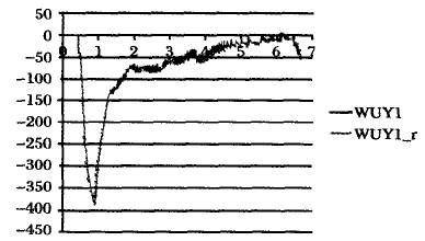
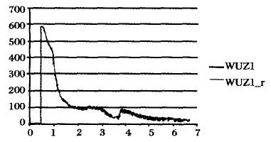
By using the given ballistic conditions as inputs, software simulations are performed and key parameters of the simulation results, such as ballistic curves, target time, control commands, and ideal ballistic data are consistent. Figure 2 shows the Y direction control command and Figure 3 shows the Z direction control instruction. In the figure, WUY1 and WUZ1 are ideal data, and WUY1_r and WUZ1_r are software simulation data.

Figure 2 Y direction control instructions

Figure 3 Z direction control instructions
4 Conclusion
The developed PowerPC-based flight control software has been verified by software and hardware tests. The software runs correctly and meets the design requirements. At the same time, the design and development flow of flight control software based on PowerPC is established. Software design ideas and design examples can provide reference for similar software development.
Optical Fiber Adapter,St Optical Fiber Adapter,Sc Flange Less Adapter,Short Flange Sc Adapter
ShenZhen JunJin Technology Co.,Ltd , https://www.jjtcl.com
