Design of a smart pet anti-lost device based on GPS
With the improvement of people's living standards, the development of social economy and the acceleration of urbanization, the pace of social aging is accelerating, the number of only-child families and Dink families and empty-nest people is increasing. Keeping pets is an indispensable life for many families. The way, here comes the loss of pets. Moreover, some pets are very expensive. Once a pet is lost, it will cause great losses to people, and the lost pets will be unmanaged and cause environmental pollution. The anti-lost devices that have been mass-produced in the market today are mainly targeted at humans, and pets are still rare and rare. The anti-lost device in this article is designed for pets, enabling fast and long-distance positioning of pets and remote alarms.
The device is based on the AT89C52 single-chip microcomputer as the MCU, combined with the wireless distance alarm of the wireless communication module nRF2401, and sends the signal uninterruptedly from the slave to the host. When the slave leaves the range acceptable to the host, the mother automatically performs the sound and light alarm. And the use of wireless communication technology and global satellite positioning (GPS) technology, low cost, can monitor a large range, easy to operate, and fast data transmission. With the GSM system, we can quickly transmit the pet's location to the user's mobile phone in an informational manner, enabling real-time monitoring of the pet.
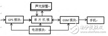
1, the system hardware designThe hardware of the pet anti-lost device is mainly composed of the following four parts, namely, the single chip control module, the GPS module, the GSM module, and the sound and light alarm module. The MCU control module is responsible for processing the overall data and processing the system according to the instructions; the GPS module is responsible for receiving the position data; the GSM module is responsible for transmitting the position information to the user; the sound and light alarm module emits sound and light when the distance between the pet and the person exceeds 200 m. Alarm. The hardware structure is shown in Figure 1.

figure 1
1.1, single chip control circuitThe system microcontroller uses AT89C52. The AT89C52 has the advantages of low power consumption and high performance. There are 8 bits of FlashPEROM inside, which can be erased repeatedly; and there is 256x8bit internal RAM; and there are low-power idle and power-down modes, sleep and wake-up functions. The anti-lost device meets the requirements of read/write speed and power consumption. The system also adds a serial port expansion chip GM8123, which realizes simultaneous communication of GPS and GSM.
1.2, GPS moduleThe system adopts the SiRFIII series, the world's first market share, the third generation of SIRF. The GPS module of the SIRF three-generation chipset has excellent performance, high sensitivity, low power consumption and short positioning time, which can help customers quickly enter the positioning application state. The chip has a positioning accuracy of 10m and can track 20 satellite orbits simultaneously. The data line interface is a six-wire connector, which requires three output lines. The first pin is connected to the DC positive power supply, the fifth leg is connected to the power ground, and the second leg is connected to the GPS. The output drive capability is 2 mA, which can be directly interfaced with the MCU interface.
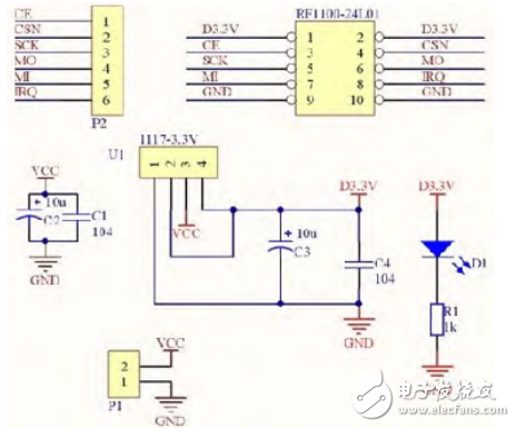
1.3, sound and light alarm moduleThe wireless RF signal transmitter of this module uses the nRF24L01 chip. The circuit includes an interface circuit of the nRF24L01 and the single chip microcomputer and its peripheral circuit. This module uses the GPIO analog SPI interface to work, and then controls the nRF24L01 chip, which solves the problem that the ST895C52 does not have an SPI controller. Another place we used here is the level shifting and voltage dividing processing circuit, which converts the power supply voltage of the ST89C52 microcontroller to 5V into the VCC pin voltage range of the nRF24L01. as shown in picture 2.

figure 2
In addition, there is an audible and visual alarm circuit. This circuit uses a PNP transistor. Q1 only functions as a switch. When the base input is high, the triode stops working, the buzzer does not sound, and when the input is low, the triode is turned on. , the buzzer sends. An alarm sounds.
Battery Charger,E-Bike Smart Charger,Golf Cart Battery Chargers,Li-Ion Battery Charger
HuiZhou Superpower Technology Co.,Ltd. , https://www.spchargers.com
