Introduction to the key issues of seven MIMO applications and measurements
Since MIMO technology can improve spectral efficiency, it has gradually become a general technology combined with OFDM. The first commercial MIMO system appeared in the WLAN, but its application hotspot has now expanded to include wireless communications including WiMAX and LTE. Because the techniques and terminology used in the various formats are slightly different, it sometimes makes it difficult to confirm what is being discussed.
The introduction of MIMO technology, that is, the mutual coupling of signals between the transmit and receive paths, opens up a new field of measurement and proposes new performance measurement requirements on the original single channel test.
This white paper is part of Agilent's "Top Ten MIMO Tips" and is designed to give users a general idea of ​​how MIMO technology is used and tested. Each section uses examples to highlight the impact of MIMO technology on radio systems or related tests. You can apply for the top ten promotional materials from Agilent (the ordering information is available at the end of this white paper).
Note 1: The spatial multiplexing technique requires at least two transmitters and two receivers. Both receivers should be located in the same location.
Some multi-antenna techniques, such as transmit and receive diversity, sometimes use the term "multiple in and out", but these techniques do not directly increase the spectral efficiency of the wireless link. In fact, spatial multiplexing technology can fundamentally increase system capacity, which is as important as diversity technology, and the two technologies are often used in combination. Therefore, the mobile station can have only two antennas, and the base station can be equipped with four antennas.
Referring to Figure 1, the key to spatial multiplexing is to simultaneously transmit different portions of user data. When a signal is transmitted through a radio channel including an antenna, some mutual coupling is inevitable.
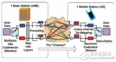
Figure 1: The use of asymmetric MIMO in mobile communications.
The ingenious aspect of MIMO technology is to avoid mutual interference of the transmitted signals, which requires us to know how the signals are coupled. In this process, we need as many receivers as there are transmitters, which leads to our first note.
Since it is necessary to convert the previously separated multiplexed code streams (referred to as codewords in 3GPP LTE) to the original information at the receiving end, it is necessary to place multiple receivers at the same position.
For signal post-processing, since the measurement software (such as the Agilent 89600 VSA) can combine IQ data from multiple inputs and then perform signal separation and analysis, there is no need to limit the placement of the receiver hardware in the same location. There is also a special case where the signal is directly connected to the analyzer via a cable and there is no coupling between them, ie direct mapping. Each stream can be recovered by connecting a single port input analyzer to each transmitter in turn.
If the frame of the signal being tested is substantially constant between frames, then a switch control can be used to capture the various signals. The Agilent N4011A MIMO Multiport Adapter is an example of a device in the WLAN that uses this technology.
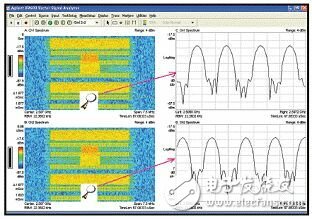
Figure 2: Different MIMO channel training subcarriers in LTE.
Note 2: MIMO technology is different in the downlink and uplink applications of wireless communication systems.
The uplink and downlink wireless links in the WLAN are symmetric, but this model has changed for mobile communication applications (as shown in Figure 1). For example, the Internet download service requires the downlink capacity to exceed the uplink capacity.
WiMAX and LTE base stations require at least two transmitters. Four or more transmitters are available in many designs to facilitate simultaneous use of MIMO technology and transmit diversity or phased array beamforming techniques. All mobile stations that support MIMO have two receivers. Receive diversity is very useful, so even if there is no MIMO technology at first, the mobile station may use two receivers.
Also shown in Figure 1 are related terms when multiplexing transmitted data signals into code streams and layers. User data is separated into multiple streams at the time of transmission. If you use both spatial multiplexing and diversity techniques, you will need to further map the codestream to the layer (shown in the grey squares in the figure). The figure shows the direct mapping process, the two streams are not deliberately coupled before transmission.
Note 3: The MIMO signal recovery process consists of two phases.
In WLAN and WiMAX, the same modulation scheme (QPSK, 16QAM, etc.) is used when user transmission data is multiplexed into a multiplexed code stream, and different modulation schemes may be used for each code stream in LTE. Therefore, there is a clear distinction between channel recovery and data recovery, which is another basic principle about MIMO.
MIMO signals are coupled to each other when transmitted over a channel, and these signals must be separated before demodulating each code stream. To this end, the receiver needs to know the channel training information of different transmitters. This channel training mechanism is called "non-blind".
There are channel training sections in both WiMAX and LTE signals. Different transmitters use different channel estimation subcarriers so that the channel estimation subcarriers of all transmitters do not use the same frequency at the same time. 802.11n was originally considered for this method, but eventually orthogonal codes were used to distinguish the transmitters.
Figure 2 shows the spectrum of the two signals of the LTE transmitter and amplifies the spectrum components of a training symbol. It can be clearly seen that the frequencies used by the LTE reference signal (RS) subcarriers are different. Unlike pilots in WiMAX, the LTE reference signal is transmitted every three or four symbols. The power of all subcarriers is the same, and their phase and time relationships are also known, so a vector mode can be created to represent the channel, which can provide coefficients for separating the streams.
Note 4: Phase difference has no effect on open-loop MIMO.
Open-loop MIMO means that the transmitted signal is directly mapped, and the signal is not coupled (precoded) using channel feedback.
In other words, the phase has an effect only when two signals are coupled twice, just as two consecutive waves of different frequencies are coupled, which is easier to understand. When synthesizing a signal for the first time, there may or may not be a known phase relationship between the two signals; this does not matter; the amplitude and phase of the two components are not affected. However, if they are coupled again, the same part will exist between the two signals and will be summed as vectors. As a result, the amplitude and phase will change, depending on the combination of the initial phase and the coupling factor, and the result is even completely offset.
This simple vector addition example illustrates why open-loop MIMO is not affected by the transmitted signal or the phase of the received signal. This is because in open-loop MIMO, the transmitted signal is not recoupled and the signal is only coupled once in the channel. This also explains why uplink MIMO still works when using two mobile stations with different locations. Incidentally, precoding cannot be applied in this case, on the one hand because the input data is valid only for each mobile station itself, and on the other hand because the phase relationship between the two mobile stations cannot be controlled.
Figure 3 is a configuration of an uplink multi-user (co-) MIMO (MU-MIMO) test. The dashed line indicates the process occurring in the actual system, and the base station controls the transmission timing and power of each mobile station so that the signals are aligned when they arrive at the base station receiver. Each mobile station adjusts its own frequency according to the reference signal of the base station. Cables can also be used in the test and other types of interference are applied to timing, power and frequency offsets to verify that the receiver algorithm is sufficiently robust.
Note 4: Cross-channel measurements can be made using a single-port input analyzer.
Most engineers start with single-input measurements, not only because of their simple measurement, but also because they provide a wealth of basic information about the operating state of the RF device. In LTE and WiMAX, there are subcarriers for MIMO channel training, and measurements using a single input analyzer are also very important.
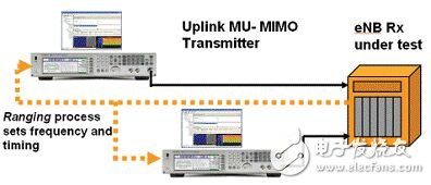
Figure 3: Uplink multi-user (cooperative) MIMO requires the system to have processing power for power, frequency and timing alignment. The Agilent MXG shown in the figure has a test configuration based on Signal Studio software that can be changed separately.
Channel isolation is part of the demodulation process test and can be easily measured. It is assumed here that the signal does not crosstalk in the transmitter. In LTE, the reference signal is not precoded, and even if precoding is applied, channel isolation does not affect the measurement. WLAN and WiMAX use direct mapping.
Signals using transmit diversity require only one receiver, and all of them can be fully analyzed with a single port input analyzer. Even directly mapped MIMO signals can be analyzed separately, although it is not possible to completely remove redundant crosstalk. By connecting the single input analyzer to each transmitter output in turn, the corresponding code stream analysis can be performed.
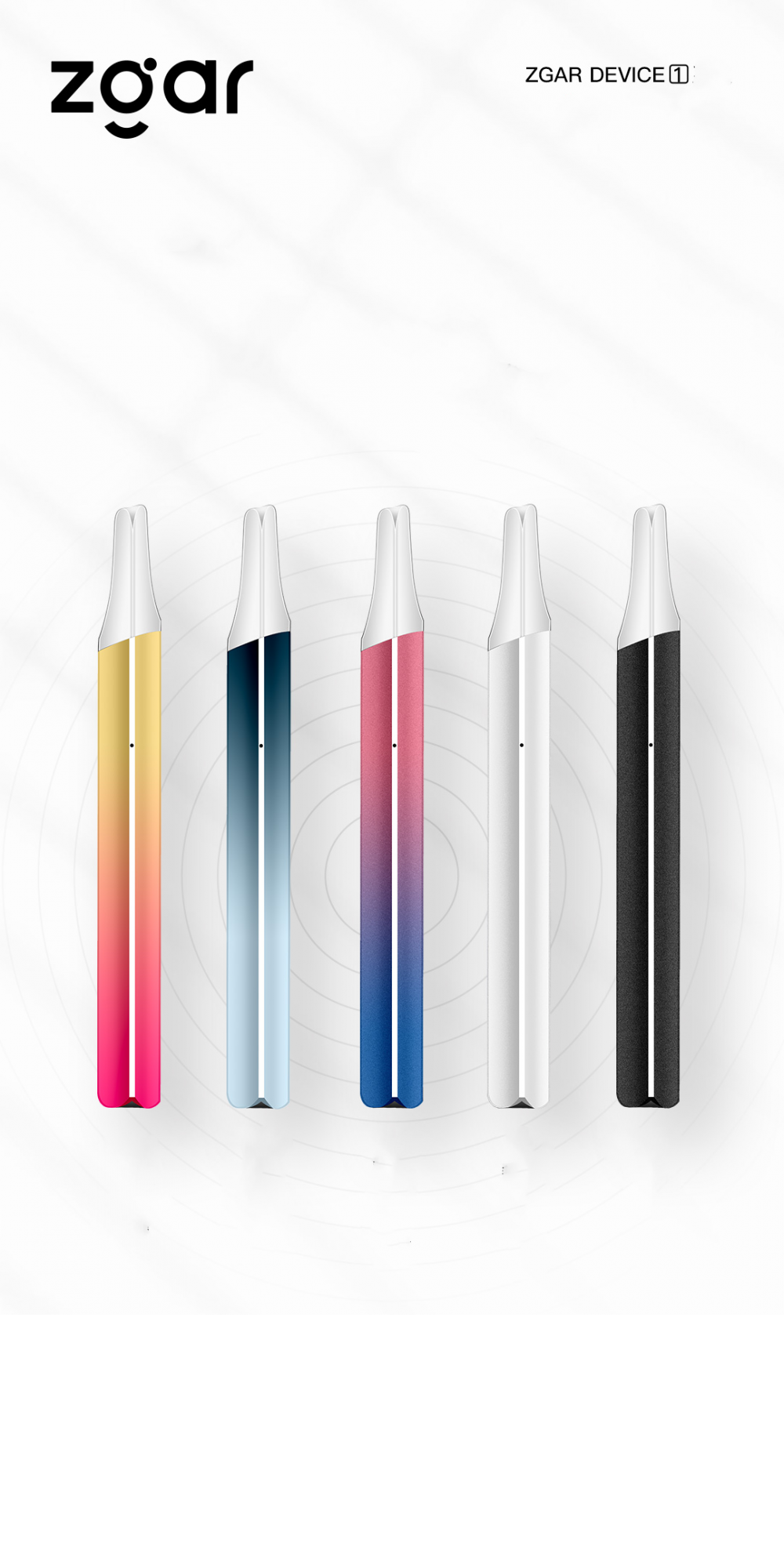
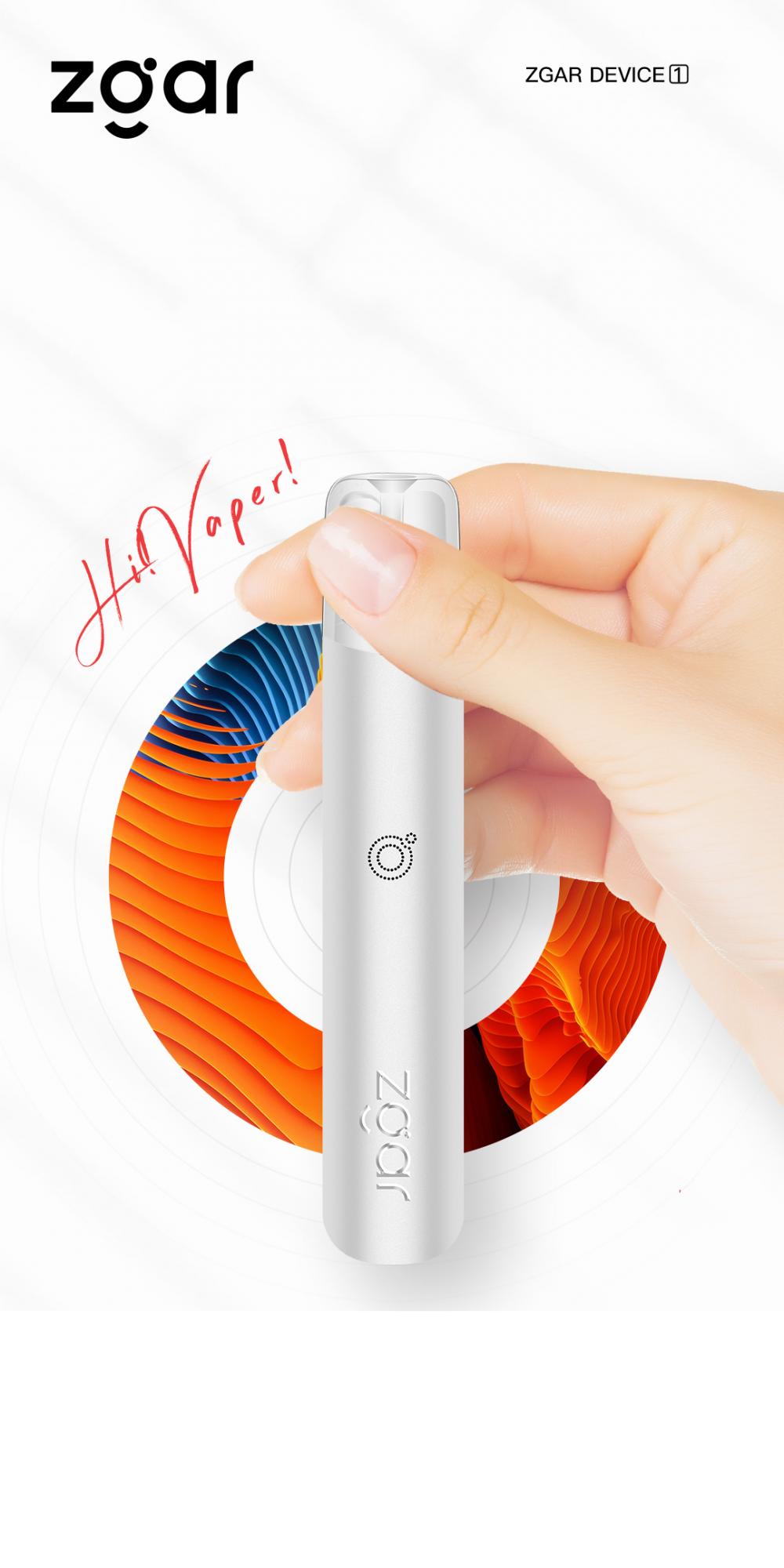
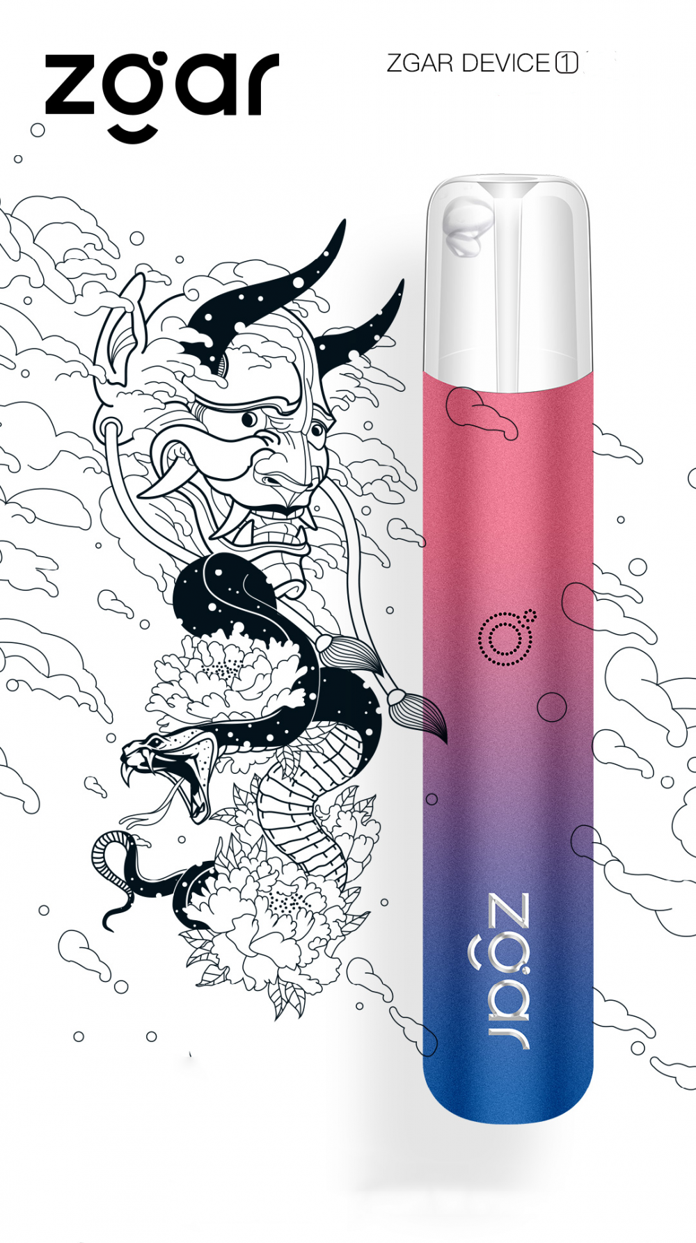
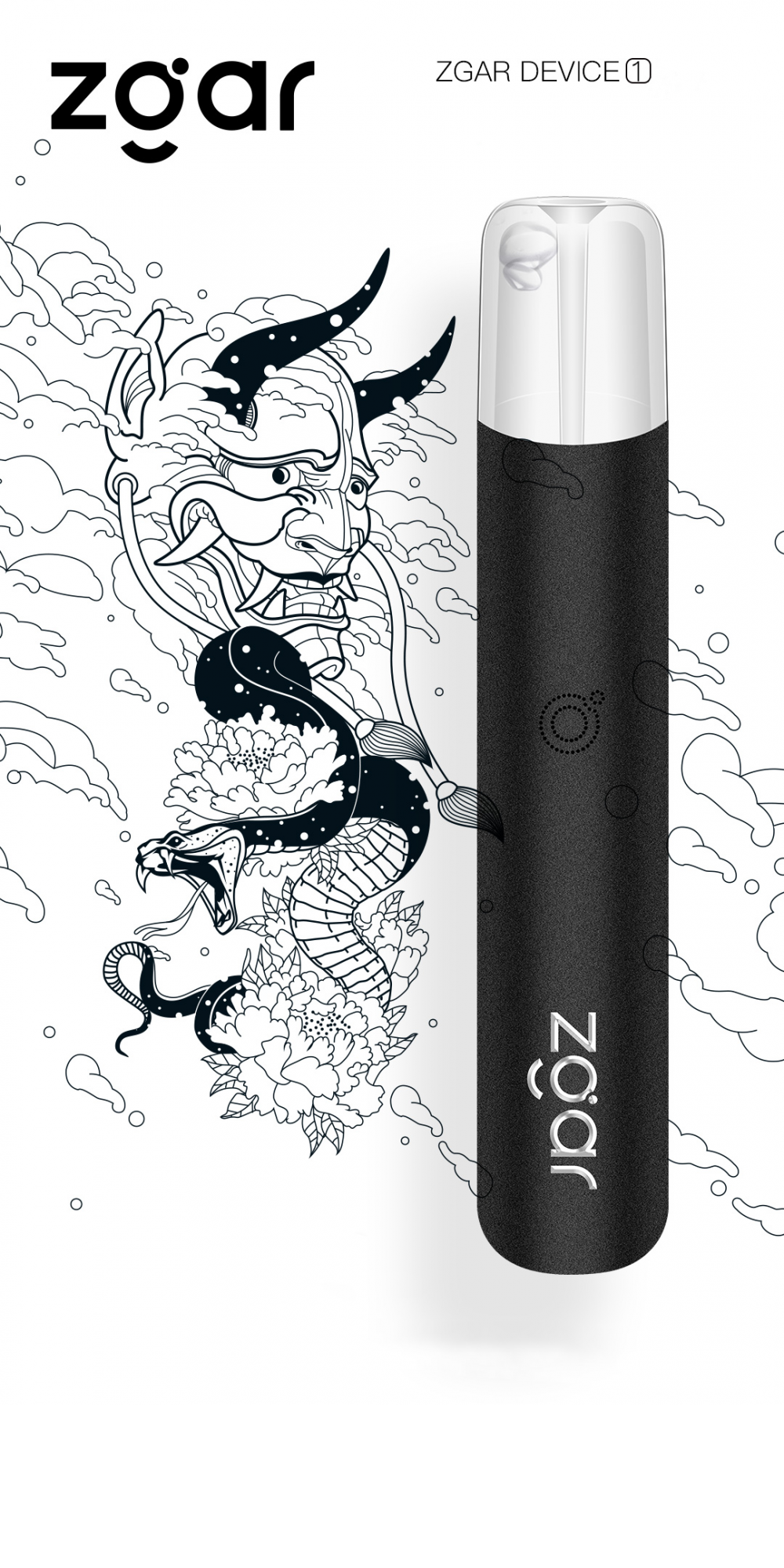
AURORA SERIES DISPOSABLE VAPE PEN
Zgar 2021's latest electronic cigarette Aurora series uses high-tech temperature control, food grade disposable pod device and high-quality material.Compared with the old model, The smoke of the Aurora series is more delicate and the taste is more realistic ,bigger battery capacity and longer battery life. And it's smaller and more exquisite. A new design of gradient our disposable vape is impressive. We equipped with breathing lights in the vape pen and pod, you will become the most eye-catching person in the party with our atomizer device vape.The 2021 Aurora series has upgraded the magnetic suction connection, plug and use. We also upgrade to type-C interface for charging faster. We have developed various flavors for Aurora series, Aurora E-cigarette Cartridge is loved by the majority of consumers for its gorgeous and changeable color changes, especially at night or in the dark. Up to 10 flavors provide consumers with more choices. What's more, a set of talking packaging is specially designed for it, which makes it more interesting in all kinds of scenes. Our vape pen and pod are matched with all the brands on the market. You can use other brand's vape pen with our vape pod. Aurora series, the first choice for professional users!
We offer low price, high quality Disposable E-Cigarette Vape Pen,Electronic Cigarettes Empty Vape Pen, E-cigarette Cartridge,Disposable Vape,E-cigarette Accessories,Disposable Vape Pen,Disposable Pod device,Vape Pods,OEM vape pen,OEM electronic cigarette to all over the world.
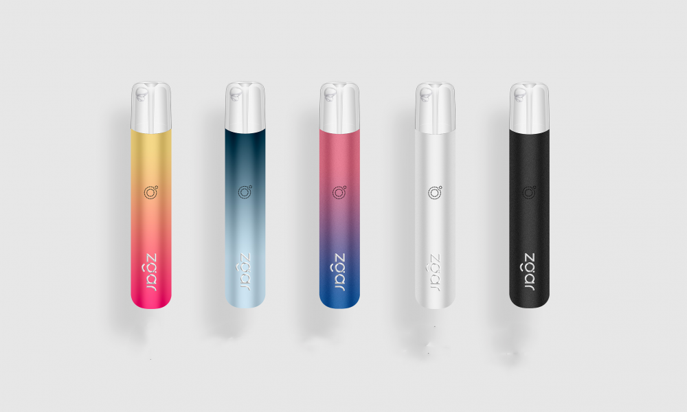
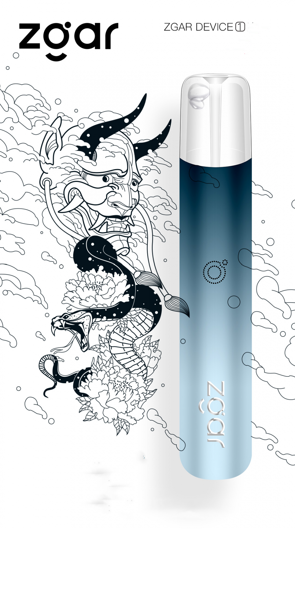
Disposable Pod Vape,Disposable Vape Pen,Disposable E-Cigarette,Electronic Cigarette,OEM vape pen,OEM electronic cigarette.
ZGAR INTERNATIONAL TRADING CO., LTD. , https://www.szvape-pods.com
