Design of LED Guardrail Control System Based on STC Microcontroller
LED guardrail tube, also known as Lid tube, is an advanced LED decorative lighting lighting product. Using red, green, and blue LEDs as light sources, microelectronics and digital technology can be used to perform color chases, gradual color transitions, grayscale changes, and seven-color changes, which can produce very rich color transition effects. The shape of the product adopts one-time molding, and the lamp tube and the base are integrated into one body, which has better water resistance and lighter weight. Widely used in bars, dance halls, buildings, squares, bridges, railings and other large-scale architectural decoration, full-color tube can also achieve a large area of ​​the lighting group control and display dynamic programs, suitable for large-scale theme night scene.
This paper presents a solution to the LED outline display of the master-slave type single-chip microcomputer. This design scheme uses the FLASH ROM and RAM of the STC single-chip microcomputer and does not require any external memory circuit. The circuit structure is simple. The AC synchronous display can be realized to drive various LED guardrail tubes and point light source devices in the current LED lighting market.
1 System working principle and overall design1.1 STC Microcontroller
STC series single-chip microcomputer is a single machine cycle clock MCU produced by Hongjing Technology. It is a high-speed, low-power, ultra-strong anti-interference 8021 single-chip microcomputer. The instruction code is fully compatible with the traditional 8051, but the speed is 8 to 12 times faster. Integrated MAX810 dedicated reset circuit for motor control, strong interference occasions. Among them STC11FXX, STC12CXX series working voltage is 4.1- 5.5 V, the operating frequency can reach 35 MHz, there is internal 512 byte RAM, cost-effective. And can carry on ISP operation through the serial port, does not need special emulator and programmer, download user's program directly, bring convenience to user's development and production and maintenance.
1.2 How Does the System Work?
The LED outline display is an LED display special effect connected by end-to-end connected LED guardrails or series point light sources, and is mostly used in the lighting engineering of building outlines. The main function of the display driver circuit is to receive digital signals from the control system and light up the LEDs to realize the display of information on the LED display. LED outline display widely used drive circuit is designed based on general-purpose integrated circuits, such as: 74HC164, CD4015, 74HC595, 68595, ULN2803, etc. Most of them are shift registers and Darlington drivers. The use of conventional drive ICs for circuit design, the principle is relatively simple, the price is cheap, the technology of the product is relatively open. The data transmission mode of the LED display screen is mainly serial and parallel. At present, the serial control technology is widely used. Each drive unit within each unit of the display screen of this control mode transmits data of only one bit (one bit for each color in the implementation) for each clock between the cascade units. In this way, there are many kinds of driver ICs that can be used. There are fewer connections between different display units, which can reduce the number of data transmission and driving elements on the display unit, thereby improving the reliability of the entire system and the ease of implementation of specific projects. .
1.3 Overall System Design
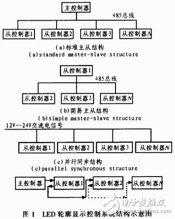
The system consists of a master controller and a slave controller. The main controller has LED display and function keys. The user selects the display effect and display speed according to the actual situation. According to the control needs can be composed of three structures as shown in Figure 1.

The structure of Figure 1(a) is a standard master-slave structure. The main controller transmits control data to each slave controller through the 485 bus. The master controller receives data from the controller and drives the LED panel as required. The structure of Figure 1(b) is a simple master-slave structure. That is, when there is no main controller or no user interaction, a slave controller acts as a master controller to send data to each slave controller. The structure of Figure 1(c) is a parallel synchronization structure. There is no main controller in the system. Each slave controller is automatically executed according to the 50 Hz frequency of the alternating current signal. Multiple slave controllers can display simultaneously.
2 system hardware design2.1 main controller hardware design
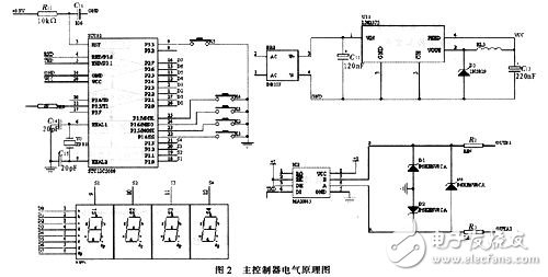
The main controller includes the minimum system of STC single-chip microcomputer, power supply part, LED dynamic display circuit, key output part, output circuit and other parts. The main controller electrical schematic is shown in Figure 2.

The smallest system uses the STC12C5608 microcontroller. The input part of the power supply allows AC or DC 9-36 V input. The DB107 AC bridge and the LM2575 high-performance regulator chip guarantee the system 5 V supply. The LED dynamic display part uses four 8-bit LED digital tubes to display the control speed "00-15" and the display output mode "00-99". The 485 output section uses three transient suppression levels to increase the actual life of the 485 chip.
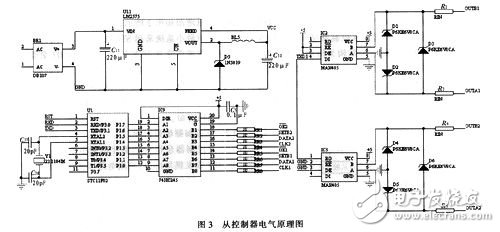
2.2 From the controller hardware design The main controller includes STC microcontroller minimum system, AC signal input part, 485 transceiver module part, output circuit 4 part integration. Master controller electrical schematic shown in Figure 3.

From the system structure chart 1, it can be seen that the 485 bus network adopts a star structure, one host and several slaves, the host only sends data, and the slave only receives data, which belongs to a single work mode. In practical applications, when the main controller is far away from the site, wiring is saved for the purpose of saving the communication and simplifying the connection structure. The star connection structure is changed to the connection mode shown in FIG.
Therefore, the 485 transceiver module of the slave controller includes a receiving module and a sending module. It can be seen from Figure 3 that the signal received by the receiving part is sent directly through the sending module without entering the MCU. Both the control requirements and the connection methods are simplified.
Data Cable,Fast Data Cable,Data Power Cable,Data Transfer Cable
Guangzhou YISON Electron Technology Co., Limited , https://www.yisonearphone.com
