Detailed explanation of machine vision and image analysis technology
Detailed explanation of machine vision and image analysis technology
1. Key Points
1. Not all vision-related projects require the services of consulting experts; with the help of hardware vendors and development tool vendors, developers who lack visual system development experience can usually complete most (if not all) of the development work, and Their company saves money.
2. Before starting the development of a vision system, you must answer about five or six questions; your answer will basically determine the hardware cost of the system.
3. As long as you choose to enable you to start device development work in a menu-driven environment, and then complete the program through graphical programming or syntax programming, you can greatly improve efficiency.
4. Accustomed to the concept that the visual system needs to be carefully cared for after installation; you often cannot foresee the various reasons why it may be necessary to adjust the algorithm after the system has been running for a while.
Successfully developing a vision-based device may require a lot of expertise, so that many developers who intend to do so are reluctant to try this kind of task, and turn to the consulting experts who build their careers through the nuances of mastering all aspects of technology . Usually, a consulting expert can not only save you several times the cost of consulting fees, but also save a lot of valuable time. Even so, the shrink-wrapped software packages developed for vision-based systems have enabled those with no machine vision or image analysis experience to calmly undertake a growing number of projects.
If you lack proper experience, the first step to taking a good step is to try to determine which tasks need outside help and which tasks you may accomplish quickly using pre-packaged software. Vendors that provide development tools and hardware can usually help you make this judgment. In many cases, the websites of these manufacturers have tools to help make such decisions. Call one of these vendors and you can usually get in touch with an application engineer who can collect information about your device. When appropriate, most manufacturers will recommend to you consulting experts who are familiar with their work. Usually, the most economical way is to use consulting help for only certain parts of a project, such as the lighting part.
Image analysis and machine vision are two related and different fields. In a sense, image analysis is part of machine vision. However, in another sense, image analysis is a broader discipline. In fact, the dividing line between these two areas is often blurred.
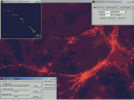
Machine vision applications often have a commercial flavor. For example, machine vision is a key part of many manufacturing processes. On the other hand, "image analysis"-as most people understand-is more likely to be applied in scientific research laboratories. Some experts say that image analysis often handles operations that are less clear than machine vision processing. An example is the characterization or classification of images of unknown objects, such as animal tissue cells in academic laboratories (Figure 1) or even in clinical pathology laboratories.

Figure 1 A research team at Howard Hughes Medical School in the Cold Spring Harbor (New York) laboratory used Matlab and its image capture and image processing toolbox to study how the mammalian brain works. Using the image capture toolbox, researchers can stream microscope images directly from the camera to Matlab, and use the image processing toolbox to analyze images over time. In order to capture and analyze at the push of a button, the researchers created a vivid graphical user interface in Matlab.
In machine vision, you usually have a general understanding of what the camera or image sensor observes, but you need to get more specific information. Product testing equipment belongs to the category of machine vision. For example, you know what kind of printed circuit board model an image depicts, but you must determine whether all components are of the correct type and are properly positioned. Determining whether the components are correct and the position is suitable certainly involves image analysis, but this analysis is more intuitive than the analysis in the clinical laboratory.
Second, the classification of machine vision tasks
Several experts divided the main machine vision tasks into the following categories:
1. Count elements such as washers, nuts, and bolts, and extract visual information from a noisy background.
2. Measuring (also called measuring) angles, dimensions, and related positions.
3. Readout includes operations such as obtaining information from barcodes, OCR (Optical Character Recognition) of characters etched on semiconductor chips, and reading out two-dimensional DataMatrix codes.
4. Compare objects, for example, compare units on the production line with the same type of KGU (known high-quality units) to find manufacturing defects such as missing components or labels. This comparison may be a simple pattern subtraction, or it may involve a geometric or vector graphics matching algorithm. If the size or orientation of the compared objects is different, the latter must be used. The types of comparison include detecting the presence or absence of objects, matching colors, and comparing print quality. The object being inspected may be as simple as an aspirin tablet, and its correct marking needs to be verified before packaging.
The above list is very specific, which may mean that you can use menu-driven graphics-based development tools to create machine vision devices instead of writing code in a text-based language such as C ++. Although developers with long-term text-based language programming for machine vision devices are generally more willing to stick to the tools they have used successfully over the years, you can indeed use one of a variety of menu-driven graphical application development software packages. Although some people in the industry are quite lame about this unwillingness to change, ask yourself if you are the first time a consultant hired to deal with a device tries to use a new software package to do your job , How are you feeling?
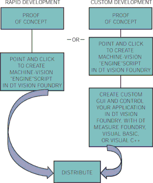
Even among the various graphics-based tools, vendors distinguish between those that really provide programmability and those that only allow users to configure the device. This configurable approach allows you to make the device run faster and provides the flexibility many developers need. Programming features can provide developers with more flexibility, but it will extend the development time-especially for those who use a tool for the first time. In some cases, both configurable and programmable methods produce output in the same language, allowing you to use programming features to modify or enhance the devices you create with configurable methods (Figure 2). The potential benefits of such flexibility are huge: you can use more powerful tools to perfect a device, and you can use basic tools to quickly make it work at the original level. This method reduces the possibility of wasting time on perfecting methods, and you later discover that these methods have fundamental flaws.

Figure 2 The main alternative technology of device development using Data TranslaTIon's Vision Foundry exemplifies the superiority of the toolbox. The toolbox allows you to quickly verify the concept using configurable menu-based interactive tools, and then improve it through programming functions device. In Vision Foundry, you can complete most programming tasks by writing intuitive scripts.
3. Adjustments that are taking place
Perhaps more important is how to use the easy interchangeability of the two methods to simplify the inevitable adjustments that are being made in many machine vision devices. For example, in AOI (Automatic Optical Inspection), you may want to exclude any UUT (unit under test) that is different from KGU. Alas, if you adopt this strategy, the inspection process will probably eliminate most of the units you produce, even if most of them have acceptable performance. Explain that a simple example of the AOI system rejecting a high-quality component due to minor differences is that the date code of a component used by the UUT is different from the date code of the equivalent component on the KGU.
At this point, you can anticipate data code problems during the design of the device and ensure that the system ignores image differences in the area containing the date code. Unfortunately, despite this, other minor differences are more difficult to predict, and you must anticipate that you will need to modify the device when you discover these minor differences. In fact, some AOI system software can make such changes almost automatically; if you tell the system that it excludes high-quality units, the software will compare the image of the unit with the original KGU, and no longer in the difference area Check the subsequent units.
However, such methods sometimes produce unsatisfactory results. Suppose that the inspection system is installed in a room where external light can enter through the window, so that the illumination of the UUT changes. Although the inspector can adapt to this change without hesitation, such a change will cause the vision system to divide the image of the same object into images of different objects, thereby causing unpredictable inspection failure. Although covering windows can prevent outside light from entering, it may be more cost-effective to adjust the test procedure to allow KGU to pass under various lighting extremes.
Even so, this example points to the importance of lighting in machine vision and image analysis. Lighting itself is a science or art. Various lighting technologies have different advantages and weaknesses, and the UUT lighting method can solve or improve common machine vision problems (Reference 1).
4. Project cost and time limit
The cost of machine vision projects varies greatly. The cost of several such projects does not exceed $ 5,000, including the cost of hardware, pre-packaged software development tools, and equipment developers ’working hours. However, such a low project cost may not include the cost of adjusting and commissioning equipment to achieve satisfactory performance. At the other end of the cost range, the project cost exceeds one million dollars. Probably the most common type of such project is a major improvement in automatic production lines in the automotive and aerospace industries. According to some suppliers, the most common project costs usually range from tens of thousands of dollars to just over 100,000 dollars. The project period from management approval to project start to the normal use of the vision system in production is usually less than six months, and often only one or two months.
Not surprisingly, almost all visual projects start with getting answers to basic questions. The answers to these questions fully determine the cost of vision system hardware: how many cameras are needed? How high must the image resolution be? Is color imaging necessary? How many frames must be collected per second? Do you need a camera that produces analog output? If so, you need to choose a frame receiving board to convert the analog signal into digital form, and when necessary, the image frame acquisition and external trigger event synchronization.
Although some frame receivers for analog cameras can receive input from multiple cameras at the same time, circuit boards that provide one interface for one camera at a time are more common. If you choose a camera with a digital interface, would you use a "smart" camera capable of image processing and image acquisition? Or is the camera sending the raw (unprocessed) image data to the host PC for processing? Also, which interface standard or bus does the digital camera use to communicate with the host PC? Digital cameras suitable for certain buses require a frame receiver. However, unlike the frame receiver for analog cameras, the frame receiver for digital cameras does not perform analog-to-digital conversion.
Hardware-related considerations may exceed these issues. Moreover, some problems use the generally correct default assumption that the main computer of the vision system is a PC running the standard version of Windows (). Machine vision systems sometimes run under real-time operating systems, while image analysis software often runs under Unix or Linux. In addition, like other real-time systems, many real-time vision systems use different CPUs than PenTIum () or Athlon () devices.
V. Camera interface
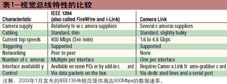
Interfacing the camera with the host computer is still a key issue in the design of vision systems. Despite the appearance of cameras with digital interfaces, although the imaging system uses IEEE 1394 (also known as FireWire and i-Link) to interface with the cameras, the choice of camera interfaces is still worthy of careful consideration. (USB 2.0, which is rapidly becoming the mainstream high-speed PC peripheral interface, is not an element of industrial imaging. This is mainly because although its 480 Mbps data transfer rate is nominally higher than the original version of FireWire, USB 2.0 The host-centric protocol is slower than FireWire for imaging.)
FireWire is a popular high-speed serial bus in consumer video systems and home entertainment systems. This plug-and-play bus uses a multi-point architecture and peer-to-peer communication protocols. The initial specification of the standard included data transmission at rates up to 400 Mbps. The data transfer rate will eventually reach 3.2 Gbps. In January 2003, IEEE released 1394b, and its proponents expect to see the 800Mbps version in the vision hardware soon. However, despite the reasonable cost of industrial FireWire cameras, its availability in consumer devices continues to increase (in consumer devices, the required resolution-and sometimes the frame rate-is higher than in industrial devices The requirements are more modest), its slim and flexible serial cable is very convenient to use, and its bus digital technology is immune to interference, but the selection of such cameras is still limited.
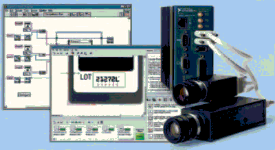
Cost may limit the popularity of FireWire in the field of industrial imaging. The cost of industrial FireWire cameras is higher than that of industrial analog output cameras with the same frame rate and resolution. On the other hand, the cost comparison between FireWire cameras and analog cameras can sometimes be misleading. In systems with a built-in FireWire port, the camera usually does not require additional interface hardware. This type of camera includes an ADC (Analog to Digital Converter), while analog cameras require a frame receiver to perform the necessary ADC functions (Figure 3).

Figure 3 The Celeron-based CVS-1454 Compact Vision System from NaTIonal Instruments exemplifies machine vision hardware designed for a factory environment. Although this system (upper right) is not a standard office PC, it contains three FireWire ports and does not require special camera interface hardware. The system is used in conjunction with the LabView graphical development environment of NaTIonal Instruments, and this development environment can quickly develop programs through interactive graphical tools. If necessary, the complete graphical programming function is then used to debug the device.
FireWire cameras use the IEEE 1394 synchronization protocol, which guarantees bandwidth and ensures that data packets arrive in the order in which they were sent (if they all arrived). The other protocols of the standard (asynchronous) guarantee message delivery but do not ensure that data packets arrive in the order in which they were sent. Each synchronization device can issue a bandwidth request every 125 μs—that is, at a maximum rate of 8 kHz. The device acting as a bus manager gives each requesting device the right to send a predetermined number of data packets within the next 125 μs.
The more synchronized devices on the bus, the less bandwidth each device can get. When there is only one camera on the FireWire bus, a 1280 x 960 pixel black and white camera can send almost 15 frames per second. A 640 × 480 pixel FireWire color camera can send approximately 30 frames per second. Although neither of these two examples seem to use the full available data transfer capacity of the bus, the number of bits per pixel and the way the camera formats data will affect the maximum frame rate. Incidentally, higher resolution is not always better. Not only are higher-resolution cameras more expensive, the frame rate is generally slower than lower-resolution cameras, but it is also easier to reveal the insignificant difference between UUT and KGU, thereby increasing the rate at which AOI systems falsely detect failures.

Six, more camera interfaces
In addition to FireWire, the interface options for digital output cameras include RS 422 parallel interface and Camera Link (Table 1). The RS 422 camera interface has not been fully standardized, so a camera-specific interface card is usually required. In the sense of interface cards for analog output cameras, these cards are not frame receivers, but they are usually also pluggable into the PCI bus of the host PC. Since sometimes more than 50 wires are required, the parallel interface proves to be unsuitable. However, RS 422 digital cameras are still popular and continue to be widely used.
AIA's Camera Link is the highest performance digital output camera interface standard. Unlike FireWire, Camera Link allows only one camera on each bus, but many PCs can accommodate multiple Camera Link buses. Camera Link can send data at up to 4.8 Gbps using SERDES (serialization / deserialization) technology on parallel combined unidirectional links, serial links, and point-to-point links. Each link can carry data from 7 channels and uses LVDS (Low Voltage Differential Signal Transmission) technology that requires two wires per link. The number of channels determines the maximum data rate of the Camera Link bus. A fully configured bus can have 76 channels, including 11 links and 22 wires, but the standard considers a bus with 28 channels and 56 channels (4 and 8 links and 8 and 16 links line). Each Camera Link bus usually requires an independent interface card in the PC.
Choosing the Camera Link bus currently involves writing additional software. Since the cards that generate the Camera Link bus in the PC are scarce and not fully standardized, the package development application package for the compact package usually lacks the Camera Link startup program. Nevertheless, if you need the compelling speed of Camera Link, then you have little choice.
Sometimes, you can use a smart camera to reduce the amount of data that the vision system must process, because the smart camera can process or compress the data it collects before sending the data to the host PC. Such a camera can sometimes reduce both the data rate between the camera and the host and the data rate between the host and the load in the host, but the cost is higher. However, you must ensure that data compression is either truly lossless or does not require data lost in compression.
Switch & Socket,Sockets And Switches,Brass Plug Sockets,Light Switches And Sockets
WENZHOU TENGCAI ELECTRIC CO.,LTD , https://www.tengcaielectric.com
