Discussion and experiment of integrated audio power amplifier IC applied to BTL method
Discussion and experiment of integrated audio power amplifier IC applied to BTL method
|
BTL (Bridge-TIed-load) means bridge load. The two ends of the load are respectively connected to the output ends of the two amplifiers. The output of one of the amplifiers is the mirror output of the other amplifier, which means that the signals applied across the load are only 180 ° out of phase. The load will get twice the voltage of the original single-ended output. Theoretically speaking, the output power of the circuit will increase by 4 times. The BTL circuit can make full use of the system voltage, so the BTL structure is often used in low-voltage systems or battery-powered systems. In car audio, when the power of each channel exceeds 10w, most of them adopt the BTL form. The BTL format is different from the push-pull format. The signal amplified by each amplifier of the BTL is a complete signal, but the output signals of the two amplifiers are inverted. A BTL amplifier is required to form a BTL amplifier with integrated amplifier blocks. However, not all power amplifier blocks are suitable for the BTL format. The several connection methods of the BTL format have their own advantages and disadvantages. The following describes each connection method by means of production experiments. The power amplifier integrated blocks used in the experiment are LM1875, LM3886, TDA1514, LM4766. Because individuals prefer the sound of LM4766, and there are many introductions in other IC application magazines. So take BLM application of LM4766 as an example.
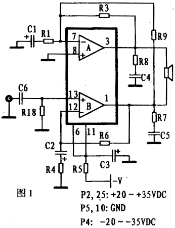
Figure 1 shows the LM4766's first BTL application connection. The input signal is input from the non-inverting input end of LM4766 amplifier B, R6, R4, C2 is its negative feedback network. The signal at the inverting input of amplifier A is introduced from the output of amplifier B via R9. And divided by R9, R1, C1. At the same time R1, C1, R3 Peng is the negative feedback network of amplifier A. Assume that the input signal at the C6 terminal is V, the gain of the amplifier B is PB = (R4 + R6) / R4, and the output voltage of the B is PB * V. The input of amplifier A is voltage-divided, and the voltage-dividing coefficient is R1 / (R9 + R1). Generally, R9 = R6 and R4 = R1 are taken in the circuit. Therefore, the voltage division coefficient is 1 / PB, the inverting input signal of amplifier A is also V, and its gain is-(R4 + R6) / R4, R3 is generally equal to R6, so the gain of A is -PB * V. The output obtained on the load is the superposition of these two signals, that is, 2PB * V. But in this form of application, there are links that affect sound effects. The first is that R9 must be strictly equal to R6, otherwise this error will be amplified by the amplification factor of A, making the output signal amplitudes of A and B very different. Second, due to the presence of C1 in the negative feedback of A, the output of A does not completely differ from the output of B by 180 ° in phase. This is the most taboo thing for HI-FI players. In the actual production and listening, I also found that the output of the circuit is really confusing in terms of positioning and layering. But whether the circuit is no-load, or there is no input signal or the signal source of the input signal has a large internal resistance, the circuit can work normally. And the additional components are only a resistor. Stability and simplicity are the characteristics of this circuit.
|
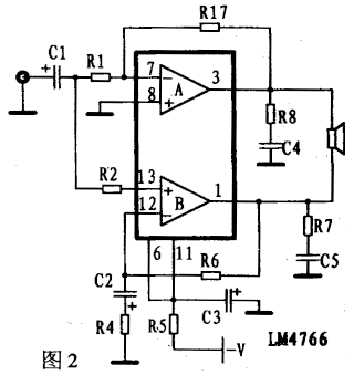
Figure 2 shows the LM4766's second BTL application connection. A acts as an inverting amplifier and B acts as an in-phase amplifier. The gain of A is -R17 / R1, and the gain of B is (R4 + R6) / R4. You can take appropriate values ​​to make the gains of the two equal. Since the input signals of the A and B amplifiers are absolutely equal in phase, even if the phase is delayed after amplification, as long as the delayed phases are equal, there will be no phase confusion after superposition. The adaptability of this circuit is not ideal. Because it has high requirements on the input signal source. The signal source must be added before the circuit is powered on, and the internal resistance must be small enough. When not connected to the signal source, A as a follower will output a DC voltage to damage the speaker. When the internal resistance of the signal source is too large, the amplification factor of A will become smaller. This connection method is suitable for the circuit system of the previous stage with low output resistance added to the circuit.
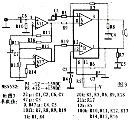
Figure 3 shows the third BTL application connection of LM4766. A NE5532 is added to the circuit. It improves the instability in Figure 2 connection. NE5532's amplifier A11 is a voltage follower, and A27 is an inverter. Therefore, the inputs of the two non-inverting amplifiers of the LM4766 are inverted, and their outputs are also inverted. C7 capacitor is used in All, which should contain no DC component in the output of A11, so A27 can use DC negative feedback, which makes the output of A27 and the output of A11 exactly 180 ° different, so there is no Said the phase delay problem. At the same time, because the output internal resistance of NE5532 is quite small, it solves the problem of instability in Figure 2. Only an IC is added to the circuit, which makes the circuit more complex.
The authors tested the above three methods using National Semiconductor's LM1875, LM3886, LM4766 and Philips TDA1514.
The first is LM1875. The maximum voltage of LM1875 can reach ± ​​30V, and the output current can reach 3A, and the maximum output power is 30W. No over-current and temperature protection circuit. In the Datasheet given by NS, it does not recommend the BTL application method. When applied to the connection in Figure 1, the sound is a bit floating. In Figure 3, when the audio input terminal is unplugged, there is a bald voice in the speaker, confirming that it is self-excited. The output power of the three circuits can reach about 80W.
Then in the way of Figure 3, make a comparison between LM3886 and TDA1514.
The maximum supply voltage of TDA1514 is. ± 30V, when the difference between positive and negative voltage exceeds 60V, the integrated block will be easily damaged. When the load is 8Ω, the maximum voltage is ± 28V, and it is recommended to use ± 24V. The maximum supply voltage of the LM3886 is ± 42V. It is recommended to use ± 35V when the load is 8Ω and ± 28V when the load is 4Ω. The power supply current should not be less than 5A. If the current is not enough, it will cause voltage fluctuations and cannot truly reflect the output power of BTL. During the test, the signal source uses a sine wave generator, adjusting its amplitude until clipping distortion occurs. The heat sink should be large enough to avoid temperature overcurrent protection.
TDA1514 must be cautious when applied to BTL mode, otherwise it is easy to excite itself. At the output of each amplifier, a 1 / 4W, 10Ω resistor and 0.047pF capacitor must be connected in series to ground. The feedback resistance (generally 27kΩ to 33kΩ) is reduced to 20k to reduce the gain. The speaker uses 8Ω. TDA1514 internal current limit protection and maximum power limit circuit, the maximum output current is about 3A. The maximum output power is 50W. When connected to BTL, it is found that the maximum power can reach about 100W, and the current limiting circuit starts to operate. The output is turned off at the peak of the sine wave. After the peak, it is turned on again. Although it is not easy to hear, it has seriously affected the sound quality. When it exceeds 110w, the power limiting circuit works, and the output is completely turned off.
|
LM3886 has a unique "SPIKE" protection circuit, which makes it better than Philips' TDA1514 in many ways. The LM3886 does not simply turn off the circuit when the output is exceeded. SPIKE protection has a conversion interval. The LM3886 also has fixed temperature detection overcurrent protection. The maximum output current is slightly larger than TDA1514. The actual maximum output power is 60W. When connected to BTL, the maximum power can reach about 120W. The sound quality of the two is indistinguishable, but when the LM3886 is applied to high voltage, its sound quality is superior in terms of robustness.
Finally, the LM4766 is connected to the experiment in the mode of Figure 3. The output power of the circuit is about 100W, and the sound quality is simply and powerful, and the dynamic range is excellent. In addition, conditional readers can go to NS's website to request free samples. The URL is: TIonal.com. In summary, when using BTL to increase the output power of the circuit, it is necessary to select the appropriate circuit form according to the system circuit, and to understand the parameters of the integrated block used in order to design a suitable application circuit.

Follow WeChat

Download Audiophile APP

Follow the audiophile class
related suggestion


