EMI filtering reduces analog application errors
How does EMI cause large DC offsets? It may be the case that many instrumentation amplifiers can exhibit excellent common-mode rejection in the frequency range up to tens of kilohertz depending on the design. However, when an unshielded amplifier is exposed to tens or hundreds of "megahertz" of RF radiation, problems can occur. At this point, the input stage of the amplifier may be asymmetrical rectified, resulting in a dc offset. After further amplification, it will be very noticeable, plus the gain of the amplifier, even reaching the upper limit of its output or part of the external circuit.
Example of how high frequency signals affect analog devices
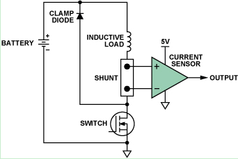
This example will detail a typical high-side current sensing application. Figure 1 shows a common configuration for monitoring solenoid valves or other inductive loads in automotive applications.

Figure 1. High-end current monitoring
We studied the effects of high frequency interference using two current sense amplifier configurations with similar designs. The functions and pinouts of the two devices are identical; however, one of them has an internal EMI filter circuit and the other does not.

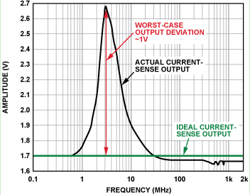
Figure 2. Current sensor output (no built-in EMI filter, forward power = 12 dBm, 100 mV/divide, DC output peaks at 3 MHz)
Figure 2 shows the deviation of the DC output of the current sensor from its ideal value as the input changes over a wide frequency range. It can be seen from the figure that the deviation is most significant (>0.1 V) in the frequency range from 1 MHz to 20 MHz, and the DC error reaches a maximum value (1 V) at 3 MHz, which is 0 V to 5 V in the amplifier. A large proportion of the output voltage range is occupied.
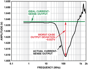
Figure 3 shows the results of the same experiment and configuration when using another pin-compatible current sensor with the same circuit architecture and similar DC specifications as the previous example, but with an input EMI filter circuit. Note that the voltage range has been expanded by a factor of 20.

Figure 3. Current sensor output (built-in EMI filter, forward power = 12 dBm, 5 mV/divider, DC output peaks at >100 MHz)
In this case, the error is only about 3 mV at 40 MHz, and the peak error (greater than 100 MHz) is less than 30 mV, and the performance is improved by 35 times. This clearly shows that the built-in EMI filter circuit helps to significantly improve the current sensor protection from the high frequency signals present at the input. In practical applications, although the severity of EMI is not known, if a current sensor with built-in EMI filtering is used, the control loop will actually remain within its tolerance.
Both devices were tested under exactly the same conditions. The only difference is that the AD8208 (see "Appendix") has an internal low-pass RF input filter on both the input and power pins. Adding such components to the chip seems trivial, but since the application is typically controlled by PWM, the current sense amplifier must be able to withstand a continuous switching common-mode voltage of up to 45 V. Therefore, to maintain accurate high gain and common mode rejection, the input filters must be closely matched.
Stereo Gaming Headset/Gaming Headset/Amazing Gaming Headsets
1). High-precision sound source position and super shocking sound effects
2). Variable Bass Boost enhances the reality and depth of explosions gun blasts and other deep sounds
Features:
1. Stereo Gaming Headset with custom logo with different color
2. Manufacture with competitive price & good quality
3. Excellent sound performance
4. Material:PVC
5. Custom packing design service
6.Use for Fashion Show and Internet bar

Stereo Gaming Headset
Stereo Gaming Headset,G230 Stereo Gaming Headset,Stereo Gaming Headset With Mic,Blue Gaming Headset
Shenzhen Greater Industry Co., Ltd. , https://www.szgreater.net
