Grasping the opportunities of circuit protection under the wave of Internet of Things
introduction
Every revolution in the information age has brought about tremendous changes in human life. As the emerging information revolution, The Internet of things has become the new favorite and development direction of the entire information industry. The Internet of Things is the Internet connected to objects. It is connected to the wireless network through interfaces such as radio frequency identification (RFID), sensors, and two-dimensional codes. It can give people "smart" and realize people and objects. The interaction can also realize the communication and dialogue between objects and objects. This network that connects objects is called the “Internet of Thingsâ€.
IoT awareness layer protection needs
The structure of the Internet of Things itself is complex, mainly consisting of three parts: the first is the perception layer, which undertakes the collection of information. The applicable technologies include smart cards, RFID tags, identification codes, sensors, etc., followed by the network layer, which undertakes the transmission of information. By using the existing wireless network, mobile network, solid network, Internet, and wide-area network, the third is the application layer, which realizes the recognition and perception between objects and objects, and plays an intelligent role.
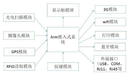
The sensory layer solves the problem of data acquisition in the human world and the physical world. The main function is to identify objects and collect information, similar to the role of skin and facial features in the human body structure. It first collects data from the external physical world through sensors, cameras, RFID and other devices, and then transmits data to the network through technologies such as Bluetooth, wifi, and 3G. FIG. 1 is a schematic structural view of a multifunction handheld terminal.

Figure 1 Schematic diagram of multi-function handheld terminal frame structure
Many devices in the IoT awareness layer have been widely used in police law enforcement, large commercial enterprises, chain stores, fast-selling goods sales, medical care, factory assembly lines, logistics, hotel catering, convention centers, and public transportation. Due to the complicated and harsh conditions in use, the requirements for product life and reliability are high. In design, manufacturers must make perfect circuit protection measures to meet the reliability and stability requirements of users.
From a design perspective, designers must take into account the unexpected occurrences of various conditions and then install protection devices on different interfaces. In this article, we will use a multi-function handheld terminal as an example to illustrate how to use the protection device.
IoT awareness layer device power interface protection
A stable power supply is the most basic condition for the normal operation of the device. However, the environment of the power interface is very complicated. Users may encounter the following situations: As more adapters are used together, a low-voltage power supply device is incorrect. When the adapter is connected to a high voltage, even the polarity of the interface is reversed; or during the normal charging process, a very high surge voltage appears at the output of the adapter due to the induced lightning. Events such as this will damage the device's power management chip.
For overvoltage and surge events that may occur, designers often use overvoltage protection integrated circuits or TVS tubes for protection. Although the integrated circuit OVP solution can solve the overvoltage problem, it does not have surge protection. While the TVS tube can achieve surge protection, it cannot be effectively protected when it is in a long-term overvoltage condition. The ideal situation is to combine long-term overvoltage and surge protection on a single device.
Poly Conen products from TE ConnecTIvity's Circuit Protection Division provide overvoltage, surge, overcurrent, overtemperature, ESD protection, and reverse power protection, as well as a separable recoverable fuse (PPTC) and regulated The higher performance, more protection and smaller size of the tube/TVS tube combination circuit has been proven in a variety of handheld and in-vehicle multimedia devices.
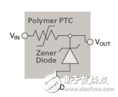
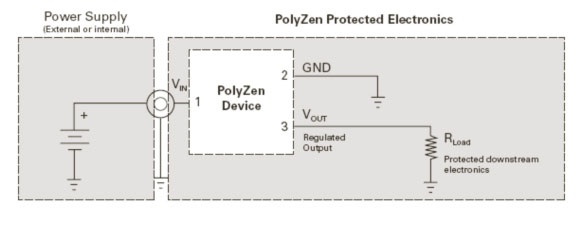
When an overvoltage fault condition occurs, after the clamp diode is broken down, its temperature will rise continuously with time. If the fault is not eliminated, or a long time overvoltage fault pulse is loaded on the circuit, this The use of low-power TVS devices does not provide effective protection, requiring high-power TVS devices to protect the back-end electronics, while high-power TVS devices mean more expensive prices and larger package sizes. The PPTC integrated in TE's PolyZen device can quickly and effectively protect against overcurrent and overheating. When the fault occurs, the Zener temperature rises. Due to the unique thermal coupling characteristics of the Zener and PPTC, the temperature of the Zener can be transmitted immediately. To the PPTC body, the PPTC itself is a thermal element that can operate in a short period of time and become a high-impedance state, so that the current of the entire circuit is limited, and the fault voltage is shared by the PPTC and the Zener. The Zener tube is well protected. PPTC can withstand fault voltage for a long time, so PolyZen can handle a long-term continuous overvoltage and overcurrent protection. This unique feature of PolyZen devices allows it to withstand large energy surges and long-term overvoltage protection in a small package size. Figure 2 is a schematic diagram of the structure of the PolyZen device. Figure 3 is an electrical schematic of a typical input interface protection circuit for a PolyZen device.

Figure 2. PolyZen device schematic block diagram

Figure 3 PolyZen device in a typical input port protection circuit
ESD protection for IoT awareness devices
IoT sensing devices also require electrostatic discharge (ESD) protection. Below are some modules or interfaces that need to be protected.
First, the touch panel module. The touch panel is touched with a finger and is highly susceptible to ESD interference. When designing the PCB, the SESD can be added to the connector location where the flexible board leads to effectively protect the ESD static generated via the connector. In addition, there is an ESD risk from the edge of the touch panel when the terminal is used. Therefore, the SESD device should be installed between the shield and the ground line to avoid signal interference on the one hand and to effectively clamp the circuit voltage on the other hand. . A single SESD is used between the power line and ground, and the other ports are protected by a SESD array.
Second, GPS, RF antenna part. Lightning in the natural environment or ESD in the human body and the environment has the opportunity to discharge into the device through the RF and GPS antennas, causing damage to the electronic components at the receiving end of the antenna. Since the RF signal is very sensitive to capacitance values, SESD components with capacitance values ​​below 0.3pF are suitable for antenna part ESD protection. In the PCB design, the SESD component should be placed close to the antenna as much as possible, and it can effectively achieve protection by using the lower clamping voltage and high surge current resistance of the front end component.
Third, the button part. Since the user needs to directly touch these physical buttons to operate, the ESD phenomenon often occurs in the gaps of the physical buttons. The design of the SESD component should be placed close to the button contact as much as possible, and it can effectively achieve protection by controlling the lower clamping voltage and high abrupt current of the IC component than the front button.
Fourth, the user interface part, such as USB interface, SIM card, TF card, etc. Users will often operate these interfaces, and each time they are plugged in, they will cause ESD problems. Therefore, it is necessary to adopt the necessary ESD protection. The USB interface speed is very fast, so it is required to maintain signal integrity after adding SESD protection. TE's low-capacitance SESD The device can be protected by USB port. For the SIM card and TF card interface, since the signal rate is not high, the SESD array using a common capacitor can be protected.
For the SESD industry trend in low-capacitance and ultra-small packages, TE offers a range of products for design engineers to choose from. TE has achieved the smallest capacitance (0.1pF) and minimum package. Table 1 is TE's SESD low-capacitance products. .

Table 1 TE company SESD low capacitance products
Review
For the power port protection of IoT-aware devices and the ESD static protection of each module or interface, TE has a complete set of solutions. For IoT circuit protection solutions, you can visit TE's portal or contact TE Circuit Protection for more detailed technical support.
This article is selected from the "Internet of Things Conference Journal", please indicate the source.
What is Car Ethernet
Car Ethernet is a new local area network technology that uses Ethernet to connect the electronic unit in the car. Unlike traditional Ethernet, which uses 4 unshielded twisted pair cables, car Ethernet can achieve a transmission rate of 100Mbit/s or even 1Gbit/s on a single pair of unshielded twisted pair cables. At the same time, it also meets the requirements of the automotive industry for high reliability, low electromagnetic radiation, low power consumption, bandwidth allocation, low latency and synchronous real-time. The physical layer of on-board Ethernet uses BroadRReach technology, and BroadR-Reach's physical layer (PHY) technology has been standardized by the One-pair Ethernet Alliance (OPEN). Therefore, it is sometimes called Broad RReach (BRR) or OABR (Open Alliance BroadR-Reach). The MAC layer of vehicle Ethernet adopts the IEEE 802.3 interface standard and seamlessly supports widely used high-level network protocols (such as TCP/IP) without any adaptation.
On-board Ethernet protocol architecture
Vehicle-borne Ethernet and its supported upper-layer protocol architecture are shown in Figure 1. Vehicle-borne Ethernet mainly involves OSI layer 1 and Layer 2 technologies, while vehicle-borne Ethernet also supports AVB, TCP/IP, DOIP, SOME/IP and other protocols or application forms.
On-board Ethernet framework
Among them, AVB is an extension of traditional Ethernet functions, which enhances the real-time performance of traditional Ethernet audio and video transmission by adding precise clock synchronization, bandwidth reservation and other protocols, and is a network audio and video real-time transmission technology with great development potential. SOME/IP (Scalable Service-Oriented MiddlewarE on IP) specifies the video communication interface requirements for vehicle camera applications, which can be applied to the field of vehicle cameras, and realizes the mode control of driver assistance cameras through apis.
As an extension of AVB protocol, Time-Sensitive Networking (TSN) introduces related technologies of time-triggered Ethernet, which can efficiently realize the transmission of automotive control information. In addition, the on-board Ethernet of the 1Gbit communication standard also supports Power Over Ethernet (POE) function and Energy-Efficient Ethernet (EEE) function. The POE function provides power for connected terminal devices while transmitting data through twisted pair cables, eliminating the need to connect external power cables to terminals and reducing the complexity of power supply.
On-board Ethernet standardization
In terms of in-vehicle Ethernet standardization, the IEEE802.3 and IEEE802.1 working groups, AUTOSAR, the OPEN Alliance and the AVnu Alliance have played a major role in promoting it.
The IEEE802.3 local area network standard represents the mainstream Ethernet standard in the industry, and the on-board Ethernet technology is developed on the basis of IEEE802.3, so the IEEE is currently the most important international standardization body for on-board Ethernet. In order to meet the requirements of the car, it involves the development of a number of new specifications and the revision of the original specifications within the two working groups of IEEE802 and 802.1, including PHY specifications, AVB specifications, and single-wire to data line power supply. In addition, AVB related to AV transmission, timing synchronization and other specifications also need to be standardized by other technical committees of IEEE, such as IEEE1722 and IEEE1588.
OPEN Alliance
The OPEN Industry Alliance was launched in November 2011 by Broadcom, NXP, and BMW to promote the application of Ethernet-based technology standards to in-car connectivity. The main standardization goal is to develop a 100Mbit/s BroadR-R physical layer standard and develop OPEN interoperability requirements.
AUTOSAR
AUTOSAR is a consortium of automotive manufacturers, suppliers, and tool developers that aims to develop an open, standardized automotive software architecture, and the AUTOSAR specification already includes the automotive TCP/UDP/IP protocol stack.
AVnu
The AVnu Alliance was formed by Broadcom in collaboration with Cisco, Harman and Intel to promote the IEEE 802.1 AVB standard and the Time Synchronization Network (TSN) standard, establish a certification system, and address important technical and performance issues such as precise timing, real-time synchronization, bandwidth reservation, and traffic shaping.
Vehicle Router,Vehicle 4G Router,Vehicle 4G Wireless Router,Vehicle Wifi Router
Shenzhen MovingComm Technology Co., Ltd. , https://www.movingcommtech.com
