Stencil printing of solder paste
With stencil printing and screen printing , all solder can be deposited on the printed circuit board in one operation step. After the squeegee is scraped on the stencil or screen, the solder paste is squeezed onto the stencil or screen. In the opening, this part of the solder paste is in contact with the circuit board. It is important that the opening of the stencil or screen is precisely aligned with the position of all the pad patterns, so for each circuit a corresponding stencil or screen must be made. The most important parameters in solder paste printing are speed uniformity, blade speed, pressure, blade angle, blade overhead height, and speed of separation from the board.
Solder paste must be thixotropic, which means that its teachings are declining during the application process. The thixotropic solder paste has a special internal structure that is mechanically affected. When this shear force is removed and the recovery begins, the internal structure is destroyed. This property ensures that the solder paste flows well onto the circuit board. The advantage of stencil printing over screen printing is its long service life, high and easy to control solder paste thickness and high accuracy due to its low overhead height. Overhead height refers to the distance between the screen or stencil and the surface of the board.
The stencil is usually made of plated metal or stainless steel, and the circuit patterns on the stencil are mostly formed by laser cutting, but can also be obtained by mechanical etching on both sides. The stencil is epoxy bonded to a rigid cast aluminum or stainless steel frame that is attached to the printer and the stencil must be precisely adjusted to maintain precise alignment with the board. By maintaining a good edge alignment with a certain stencil thickness and blade hardness, a stencil printing can obtain a thick solder paste layer with a larger thickness, the surface between the solder paste and the substrate, compared to screen printing. Tension (adhesiveness) ensures that the solder paste remains adhered to the surface of the board as it passes through the screen or stencil surface and the squeegee is separated from the board.
1. Board fixing fixture
The board fixture secures the board during the printing process. It often provides this functionality through a vacuum panel located beneath the stencil. The purpose of the vacuum panel is to support the board during the printing process. Keep it level. If there are certain components underneath the board, space is required at the designated location of the vacuum panel or a bracket is placed to protect these components. Alignment marks marked on the stencil and board can be used to align the board fixture and stencil. This alignment mark is also called the reference.
2. Scraper
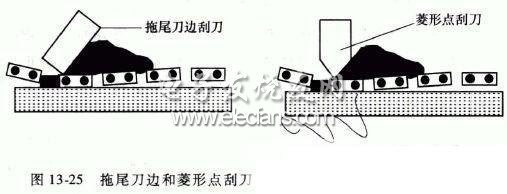
The scraper can be made of thin metal. It can be evaluated by making a uniform solder paste layer on the paper by placing a piece of paper underneath to determine whether the setting is correct and the pressure generated is uniform. . The best way to print is to use less pressure at the beginning of printing without overstressing the pressure, as this can damage the template. Solder paste should be rolled in front of the blade during printing, but not a layer of solder paste on the template. If a layer of solder paste is left on the template, the pressure of the blade is too small, and the roll in front of the blade The diameter is approximately 15mm. Polyurethane scrapers have a trailing edge or a diamond cross section, as shown in Figure 13-25. They have several hardnesses. Sharp blade edges are required in all types of scrapers. Periodic re-sharpening corrections are required.

Various references describe the contact angle of the blade, which ranges from 45-80°. Usually a larger print angle will make the solder paste pass through the template less, and a smaller print angle will result in alignment. decline. When the solder paste is deposited on the board, the stencil behind the squeegee will immediately lift (bounce back) and return to the original overhead position, otherwise the stencil will erase the solder paste deposited on the board.
Fleck (1994) describes the process of fabricating a stencil using a laser-cutting process that provides more control over the amount of solder paste deposited on a printed circuit board pad, if a clean-free solder paste is used to attempt to mount a tight pin. This control is even more important when it comes to components. Since there is no cleaning step to remove potential solder balls, the requirements for printed deposition are necessarily higher.
The tight pin pitch printing feature is characterized by a narrower aperture. At this time, the metal scraper becomes the only practical choice. The degree of solidity overcomes the wear problem, and it does not cause cracks to dig the solder due to deformation. The main danger of this type of scraper is that it has a large impact on the stencil and may cause the stencil to be damaged.
Pwm Wind Solar Hybrid Controller,Waterproof Solar Charge Controller,auto solar charge controller
GuangZhou HanFong New Energy Technology Co. , Ltd. , https://www.hfsolarenergy.com
