Hydraulic system pneumatic schematic diagram and solenoid valve detailed explanation
Engaged in the industrial control industry, it is inevitable to contact hydraulic and pneumatic schematics, and hydraulic and pneumatic professional and industrial control belong to two different professions. Many engineers who are engaged in industrial control cannot understand the hydraulic and pneumatic schematics, which leads to various difficulties in programming. In fact, the hydro-pneumatic schematic has many similarities to the electrical schematics we often draw. As long as you can read the circuit diagram, it is very simple to see the hydro-pneumatic schematic. Now from the perspective of industrial control, how the industrial control person can interpret the hydraulic schematic.
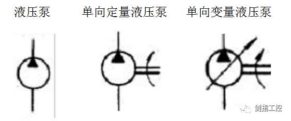
First, the hydraulic system can be divided into: power components, actuators, control components, auxiliary components, working media, and so on.Power Element: The pressure energy that converts mechanical energy into a liquid. Common components: hydraulic pump

Actuator: converts the pressure energy of the liquid (pressure p, flow q) into mechanical energy (torque T, speed, or linear motion speed, output force F). Common components: hydraulic motor, hydraulic cylinder

Control element: Controls the pressure, flow and direction of the liquid to control the output force, speed and direction of the actuator, overload protection and program control. Common components: hydraulic valve
Hydraulic valves are divided into: directional control valves, pressure control valve flow control valves;
Divided into control mode: on-off valve, proportional control valve, servo control valve, digital control valve
Classified by structure: slide valve, cone valve, ball valve, nozzle flapper valve, jet tube valve
According to the manipulation method: manual, mobile, electric, hydraulic and electro-hydraulic
Electric valves can be further divided into: stepper motor control, electromagnet control and servo motor control.
The solenoid valve controlled by the electromagnet is briefly described below.
Two: the common meaning and name of the solenoid valveThe solenoid valve symbol has the same fixed symbol and name as the circuit diagram symbol. We only need to remember a few symbol codes and names.
There are two international standard methods for solenoid valve symbols, namely digital standard method and letter standard method. Their relationship is 1=P=air inlet, 5=R=exhaust port, 3=S=exhaust port. 2 = a = working port 1, 4 = b = working port 2. There are 82, 84, 12, and 14 other, which are not stated.
The following is a brief introduction to the hydraulic valve marked with letters:
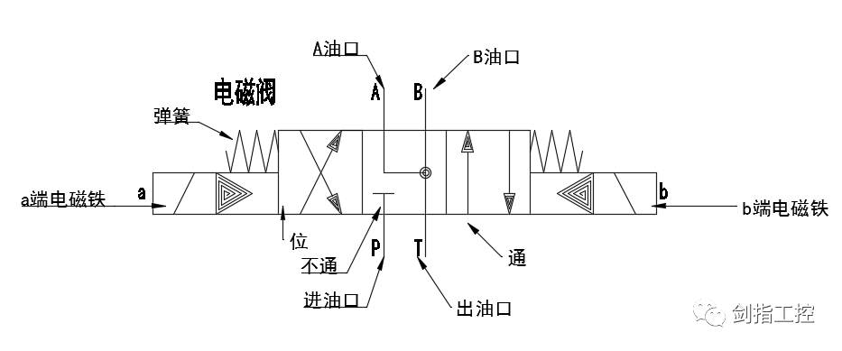
P——The inlet or inlet of the valve and the system for the oil or gas path
T/O——The oil outlet or air outlet of the valve and system supply line or air line (some are indicated by R/S)
A, B——the working port of the port or port where the valve is connected to the actuator
Coil (electromagnet) - the power supply end of the solenoid valve
Bit - also known as the work position, with a box to indicate the working position of the valve, there are several boxes to indicate that there are several "bits", but also that the valve has several working states
Pass--the number of interfaces externally connected to the box. If there are several interfaces, it means a few "passes".
The arrow inside the box indicates that the oil or gas path is on, but the direction of the arrow does not necessarily indicate the actual direction of the liquid or air flow.
The symbol "┻" or "┳" in the box indicates that the road is blocked.
As shown below:

The solenoid valve is a three-position four-way valve, and the three positions indicate that the valve has three blocks, and the arrows in each box point differently, indicating that the state is different when it is turned on. There are P, T, A, B external connection ports, called four-way, which represent the oil inlet, oil outlet, A oil port, and B oil port. The positions of the four wires in each position are fixed. . The a and b end electromagnets are our power supply terminals, and the springs are used for resetting.
Generally, valves have two or more working positions, one of which is the normal position, that is, the position where the spool is not subjected to the operating force. The middle position in the upper graphic symbol is the normal position of the three-position valve. Simply put, the initial position where the valve is not powered or not working. The two-position valve with spring return is in its normal position with the path state in the box close to the spring. When drawing the system diagram, the oil/gas path should normally be connected to the normal position of the reversing valve.
When the valve works as the intermediate normal position, the P inlet port is blocked and no oil enters; the A and B ports are connected to the T outlet port, and the actuators connected to the A and B ports are in a freely acting force. status.
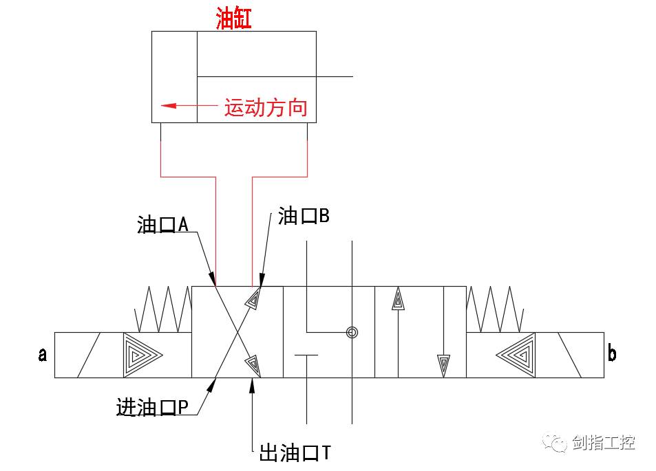
When the valve is working in the left working position, the oil inlet port P is oiled to the oil port B connected to the actuator, and the amount of oil in the chamber is increased; the oil port A is discharged to the oil outlet T, and the amount of oil connecting the oil port A is cut back. The actuator moves to the end of the connecting port A as shown below:

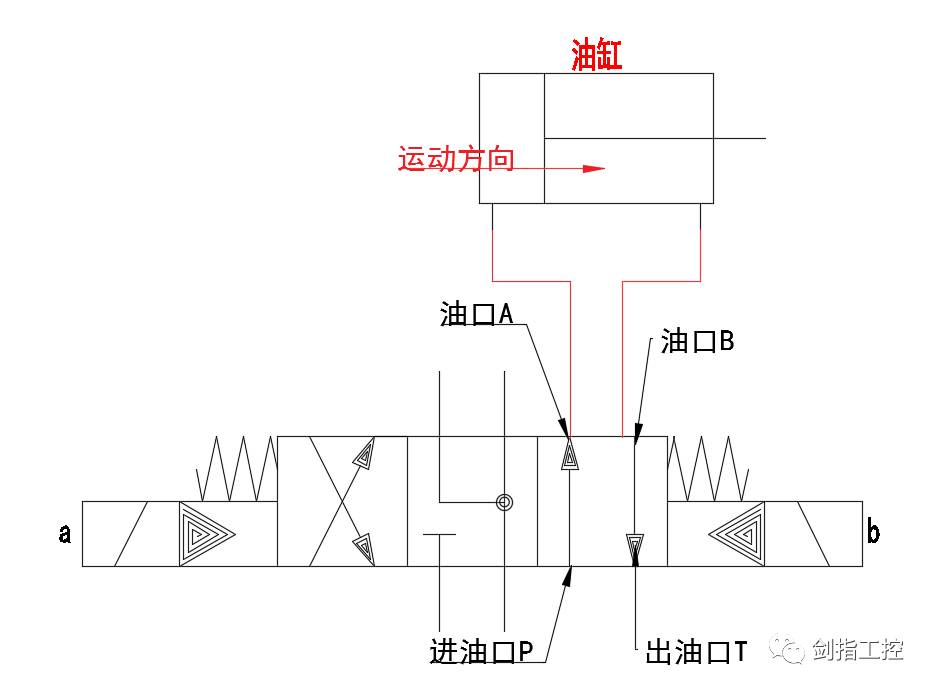
When the valve is working in the right working position, the oil inlet port P is supplied with oil to the port A connected to the actuator, and the amount of oil in the chamber is increased; the port B is oiled to the oil outlet T, and the amount of oil connecting the port B is cut back. The actuator moves toward the B end of the connecting port as shown below:

The working principle of this three-position four-way valve is similar to the principle of our circuit diagram. Just remember a few passes, then look at the schematic of its position, the working principle is clear at a glance. There is no longer any need to worry about whether we need to always supply power or a short-term power supply when we connect the hydraulic solenoid valve when we write the program.
best e cig,e cig vaporizer,best e cig vape,e cigaratte,vape cigratte
Newmax Electronics Co.,Limited , https://www.advvape.com
