Method for realizing voltage detection based on TL431 simple circuit
Voltage detection is an essential function of fiber-optic communication equipment. It is a source of information to realize the power-off warning of the equipment, so as to report the power-down warning to the background server or network management. Although there is a dedicated voltage detection chip, the cost of the communication equipment decreases. The pressing pressure is to find alternative circuits that are cheaper and more stable, which reduces costs and increases the competitiveness of products in the international market.
1. Optical fiber communication equipment 1.1, fiber-to-the-home FTTH introductionFiber to the Home (FTTP), also known as Fiber to the House (FTTH), refers to a broadband communication system that is based on fiber optic cable and uses optoelectronics to deliver multiple high-end services such as triple play, broadband Internet and television. Delivered to the home or business, the following is abbreviated as FTTH to represent the fiber to the home.
There are two main types of FTTH wiring structures: one is a point-to-point form topology, one fiber is used from the central office to each user; the other is a point-to-multipoint form topology passive optical network (PON), which A point-to-multipoint topology can effectively reduce the number of optical transceivers and the amount of fiber used for routing, while reducing rack space.
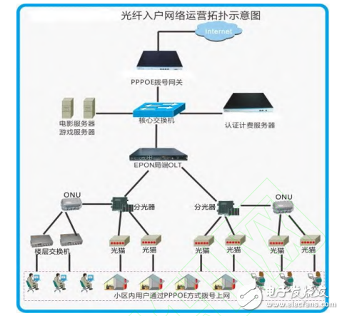
1.2, fiber optic communication layoutAccording to the point-to-multipoint passive optical network solution, an example is given in the following figure. The following figure (Fig. 1) is a typical layout of a passive optical network, and an optical line terminal (OLT) manages a large number of home users (ONUs). The optical line terminal is placed in the equipment room of the cell or unit, and each optical module is placed in each household or office, and the core switch is placed in the equipment room of the telecom operator. All ONU communication data must be aggregated to the OLT, sent by the OLT to the core switch, and the core switch to the network. As can be seen from the figure, all ONU management is done through the OLT.

figure 1
2, circuit design 2.1, voltage detection chip MAX708Overview
The MAX708, a reset chip manufactured by MAX, is a voltage-sensing control chip with a microprocessor that can simultaneously output two levels of reset signals, that is, both active high and active low. There are three cases where the reset signal can be triggered by a separate comparator, VCC voltage or manual reset input.
The MAX708 has a voltage comparator embedded in it. The voltage comparator can be used to monitor the external input voltage signal. It outputs high and low levels according to the voltage comparison result, and provides voltage drop alarm function for other CPU processors. This chip is widely used for power switching. In the system that requires an early warning, such as sending an alarm to the operator or a normal shutdown.
The MAX708 is available in SO-8 or TSSOP-8 surface mount and offers three selectable field values.
performance
The reset signal has RESET and RESET# signals, representing high level reset and low level reset, respectively.
The voltage detection field of the power failure or low power warning is 1.25V, which is input to the chip's independent comparator.
Manual reset signal input
The chip operates with a supply current of 100uA
The reset field values ​​are optional: 2.63V, 2.93V, 3.08V
Provides a valid RESET signal when VCC=1V
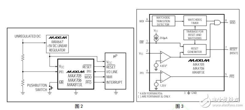
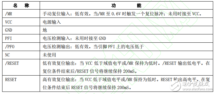
Typical application is shown in Figure 2. The internal equivalent circuit is shown in Figure 3. Since its application circuit and internal equivalent circuit are similar to the MAX706, it is represented by the typical application circuit and internal equivalent circuit of the MAX706:

Table 1 pin definition

From the equivalent circuit diagram 3, when the PFI input voltage is greater than 1.25V, the /PFO output is low. When the PFI input voltage is less than 1.25V, the /PFO output is high; the PFI externally inputs the voltage through the main board (generally DC 12V) is divided into PFI after input voltage, and 1.4V is applied to the PFI pin after 12V partial voltage. Once 12V is powered off, when 12V falls to 10V, the PFI pin level becomes 1.25V, reaching the domain value of 1.25V. The comparison is made by the internal comparator of the chip. The threshold is lower than the internal reference voltage, and the comparator outputs a low level, which causes the /PFO output to be low. The power supply voltage of the main board continues to be powered down by 10V, but falls from 10V to 5V. In the process, the switching power supply circuit in the motherboard can also ensure the normal operation of the motherboard. In the process of 10V falling to 5V, the /PFO outputs a low level to the processor, the processor is in normal operation, and the /PFO signal can be processed immediately. And issue a warning.
Butt Connector,Lugs Insulated Female Connectors,Insulated Female Connectors,Non-Insulated Spade Terminals Wire Connector
Taixing Longyi Terminals Co.,Ltd. , https://www.lycopperterminals.com
