Passive Intermodulation of WCDMA System_Two Port Passive Intermodulation Measurement System
 The third-order intermodulation distortion produced by two frequencies is a common problem in modern communication systems. When two (or more) carrier-frequency signals in a system pass through a passive device, such as an antenna, cable, filter, and duplexer, due to unreliable mechanical contact, cauterization, and surface oxidation, etc. The connection of different materials creates nonlinearities, which are like mixing diodes.
The maximal intermodulation products produced by the two carrier frequency signals (F1 and F2) and their second harmonics (2F1 and 2F2) are third-order intermodulation distortions (2F1-F2 and 2F2-F1). The typical index of the third-order intermodulation product (IM3) is that when two +43 dBm carrier frequency signals are simultaneously applied to the device under test (DUT), the resulting IM3 value is not greater than -110 dBm, which is -153 dBc.
Third-order intermodulation distortion will degrade the performance of the communication system. Excessive third-order intermodulation products in the transmitted signal can interfere with other receivers, eventually causing the receiver to malfunction. In general, designers are more concerned with the intermodulation test of active devices. However, with the development of communication systems and the improvement of system quality, more and more attention has been paid to passive intermodulation measurement.
Passive intermodulation of WCDMA systems
In GSM 900/1800 and 800 MHz CDMA communication systems, the third-order intermodulation products generated by the transmitting frequency band fall into their respective receiving frequency bands. The WCDMA band is different, and the third-order intermodulation products generated in the transmission band (2110 MHz to 2170 MHz) do not fall into its own reception band (1920 MHz to 1980 MHz), but fall into the transmission band. The following mathematical calculations can be used to verify this phenomenon.
The third-order intermodulation product FIM3 = 2F1-F2, where F1 = [2110, 2170] and F2 = [2110, 2170]. To prove FIM3≠[1920, 1980], just look for the value range of FIM3, and then see if there is intersection between this set and [1920, 1980].
Request FIM3 range of values, the key requirements of its minimum FIM3 (min) and the maximum value FIM3 (max): FIM3 (min) = 2F1min-F2max = 2 & TImes; 2110-2170 = 2050; FIM3 (max) = 2F1max-F2min =2&TImes;2170-2110=2230. Visible, FIM3 = [2050,2230] and [1920,1980] no intersection, that is to say FIM3 ≠[1920, 1980].
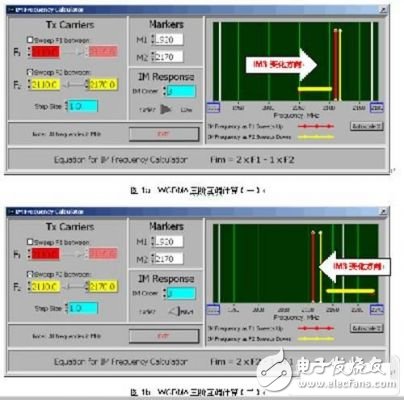
Through the calculation tool, the third-order intermodulation trend of the WCDMA band can also be characterized. This change trend is consistent with the above calculation results, as shown in Figure 1.

Figure 1a shows the changing trend of IM3 from 2050.0 to 2110.0MHz when F1 = 2110.0MHz, F2 changes from 2110.0MHz to 2170.0MHz; Figure 1b shows that when F1 = 2110.0MHz, F2 changes from 2170.0MHz to 2110.0MHz. When IM3 changed from 2230.0 to 2110.0MHz.
From the above situation, it can be found that regardless of how F1 and F2 change in the range of 2110.0 MHz to 2170.0 MHz, the IM3 will not fall into the 1920.0 MHz to 1980.0 MHz frequency band but will fall to the 2050.0 MHz to 2170.0 MHz frequency band. In addition, the seventh-order intermodulation of WCDMA system will fall into its receiving frequency band, such as IM7=4&TImes; 2110-3&TImes; 2170=1930MHz, this question will be discussed in another article.
In a WCDMA system, if a passive intermodulation signal of -110dBm is generated in the transmission band, that is, an interference signal, this may affect the system because this value is already larger than the minimum amplitude of the useful signal in the system.
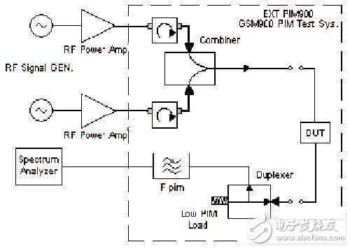
In GSM 900/1800 and 800 MHz CDMA communication systems, IM3 generated by the transmitting frequency band will fall into the respective receiving frequency band. In these three systems of passive intermodulation measurement systems, duplexers and filters are commonly used to extract the IM3 value. Figure 2 shows a typical two-port device passive intermodulation measurement system (BXTPIM900) in the GSM900 receive band.

Figure 2 BXTPIM900 two-port passive intermodulation measurement system
When F1 and F2 pass through the DUT, the output of the DUT has four frequency components F1, F2, 2F1-F2, and 2F2-F1, where F1 and F2 are directly absorbed by the high-power, low-intermodulation load, while 2F1-F2 and 2F2- F1 is extracted by the duplexer and the filter is to further filter F1 and F2 to improve the dynamic range of the spectrum analyzer. Since the third-order intermodulation products all fall into the receiving band, standard duplexers and filters can be used.
The WCDMA band is different. From the above analysis, we have found that the IM3 value generated by the transmitting band (2110 MHz to 2170 MHz) falls to the transmitting band, that is, the IM3 value is very close to F1 and F2. In this case, the duplexer cannot be used to extract IM3 but other methods are used.

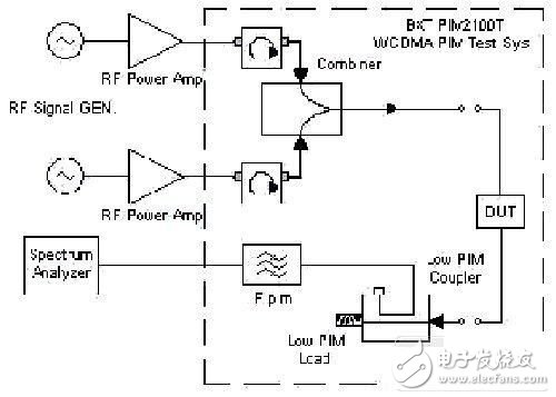
Figure 3 refers to the IEC recommended emission band IM3 test method.
BXTPIM2100T WCDMA Two-Port Passive Intermodulation Measurement System
Figure 3 BXTPIM2100T WCDMA Two-Port Passive Intermodulation Measurement System
Two 46dBm CW signals are synthesized by a combiner into a transmission line and added to the DUT. The synthesized signal is passed through the DUT and is absorbed by a low intermodulation load. The -30dB signal is coupled out of the directional coupler through a Adjust the bandpass filter and test the allowable IM3 value on the spectrum analyzer.
From the test principle and method, the passive intermodulation test is not complicated, but it is not easy to complete an accurate test. When building a test system, pay attention to every aspect of the system.
(1) Power amplifier. In some PIM test systems, usually 43dBm power amplifiers are used. However, in WCDMA systems, higher peak power requirements for WCDMA signals place higher demands on the system's transmit power, which means that passive components in WCDMA systems will operate at higher RF power levels. Therefore, the power in a WCDMA passive intermodulation measurement system should be as large as possible, but due to the limitations of the amplifier cost and the power capacity of the combiner, a power amplifier of 46-47 dBm is usually used.
(2) Directional couplers. The use of a 30dB directional coupler takes into account that the sum of the F1 and F2 power input to the spectrum analyzer is as small as possible, so that the spectrum analyzer can operate at a safe level, and second, high power signals can be prevented from generating active interaction in the spectrum. To adjust, F1 and F2 can be suppressed to 0dBm or less by a bandpass filter.
(3) Filter. Since the third-order intermodulation product of WCDMA falls in the transmitting band, it is not possible to extract the IM3 component with a fixed filter. An adjustable band-pass filter can be used to accomplish this function. The Q-value of the band-pass filter should be as high as possible. A five band pass filter is recommended.
(4) Test system. From the passive intermodulation test principle, the test system should be solidified in a standard chassis. This can avoid a lot of uncertainties affecting the test accuracy, such as the use of semi-flexible cable instead of braided cable, a reasonable grasp of the connection torque of the connector, to prevent the device in the system caused by contact and other factors such as poor contact with the test.
(5) Test the cable. In the entire system, the only thing that needs to be moved often is the DUT and the cable connecting the DUT. Although the self-passive intermodulation performance of wrinkled and semi-flexible cables is very good, these cables cannot be used as test cables because they cannot be bent repeatedly. Therefore, passive intermodulation test cables can only be made using special braided cables or microwave cables, such as RG393, which can achieve a PIM value of -165 dBc.
Good communication quality is guaranteed by the carrier frequency/interference ratio (C/I) indicator, and the "I" value should be as low as possible. Ideally, the "I" value should be less than the noise floor of the receiver. From the above analysis, it can be proved that one of the main causes of unwanted interference is passive intermodulation.
The WCDMA system is currently in its infancy and there are no standards for passive intermodulation measurement. At present, only a few companies are engaged in the research of WCDMA passive intermodulation test. However, as this indicator will directly affect the production and manufacture of passive devices, further affecting the performance of the system, there are more and more passive device manufacturers and base station manufacturers are beginning to care about this indicator, I believe in the near future In the future, a suitable passive intermodulation measurement system will be born.
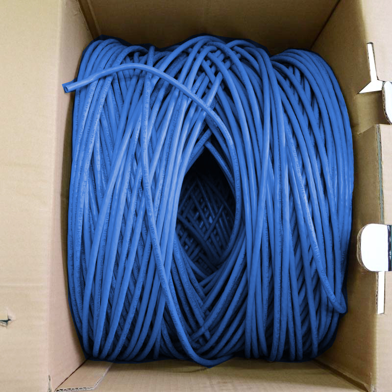
Lan cable include CAT7 Lan Cable, cat6a cable, cat6 cable, cat5e cable.
The length of the lan cable are 1000ft (305m), the usable part of a box cable is about 300 meters. To press the RJ45 connectors, usually needs to consider the consumption of part of zhuan degree, so one box of lan cable is 305 meters.
Home Network Cable is called "twisted pair". About twisted pair:
Twisted Pair (TP), the most commonly used transmission medium in comprehensive wiring projects, consists of two insulated copper wires. By stranding two insulated copper wires together at a certain density, the radio waves emitted by each wire during transmission are offset by those from the other wire, effectively reducing the degree of signal interference.
Twisted-pair wires are usually made of two 22-26 insulated copper wires wrapped around each other, hence the name "twisted-pair wire".In practice, twisted pair consists of several pairs of twisted pair wrapped together in an insulated cable sleeve.If one or more pairs of twisted-wire is placed in an insulating bushing, it becomes a twisted-wire cable. However, in daily life, "twisted-wire" is generally referred to as "twisted-wire".

Lan Cord,Lan Wire,Lan Cable Connector,Flat Ethernet Cable
Shenzhen Kingwire Electronics Co., Ltd. , https://www.kingwires.com
