SMC host interface module design is imported into the Xilinx environment.
The SMC Host Interface Module easily integrates designs created with the Synphony Model Compiler into the Xilinx Embedded Platform.
The Synphony Model Compiler (SMC) is a model-based tool from Synphony that integrates designs created in Simulink® and MATLAB® to generate optimized RTL for ASIC and FPGA target applications. SMC includes a comprehensive and comprehensive library of advanced models for creating math, signal processing and communication designs in the Simulink environment. This library simplifies the capture and functional debugging of fixed-point single-rate or multi-rate algorithms in an advanced model design environment. The SMC RTL generation engine can automatically create RTL using these proven models to achieve multi-architecture hardware implementation and rapid exploration for footprint, performance, power, and throughput trade-offs. SMC's advanced synthesis engine uses top-level design and MATLAB language input to generate RTL optimized for selected hardware targets. In addition, SMC can automatically generate an RTL test platform for the design, coupled with bit and cycle high-precision C model and SystemC package program, can be used to verify the generated hardware in the SystemC simulation environment.
In many applications, designers create some peripherals to perform some signal processing functions and must configure the peripherals through a host processor such as the Xilinx MicroBlazeTM soft processor core. Host processors typically connect to peripherals using standard bus interfaces such as AMBA® AXI4 or AXI4-Lite. The SMC library includes a host interface module that can implement a slave interface of the host processor. The host interface module not only supports AXI4-Lite, APB, general-purpose interfaces, and Avalon-MM bus interface protocol standards, but also configures the SMC design by implementing the necessary memory-mapped registers, including FIR filter coefficients, numerically controlled oscillators ( The frequency and phase settings of the NCO) and the FFT length of the FFT modules of various lengths. In addition, the host interface module can use any desired sampling frequency when implementing the memory mapped control register, and can be asynchronous with the bus interface clock. You can specify the bus interface and memory mapping settings in the UI of the host interface module. Designers can use the host interface module to connect the SMC design to the bus interconnect or bus master.
Now let's take a closer look at how to import and integrate peripherals designed with the SMC host interface module into the Xilinx Embedded Development Kit (EDK) project. In addition, we will demonstrate how to simulate the data transfer from the MicroBlaze host processor to the peripheral AXI4-Lite bus connected via a standard bus interconnect. There are four main steps in this process:
1. Create peripherals in Simulink using IP, host interface modules, and the SMC RTL generation engine to generate optimized RTL implementations for the design;
2. Import the peripheral into the Xilinx EDK project and integrate it with the rest of the design;
3. Develop software applications in the SDK;
4. Generate an RTL and simulate it to check if the hardware and software functions are correct.
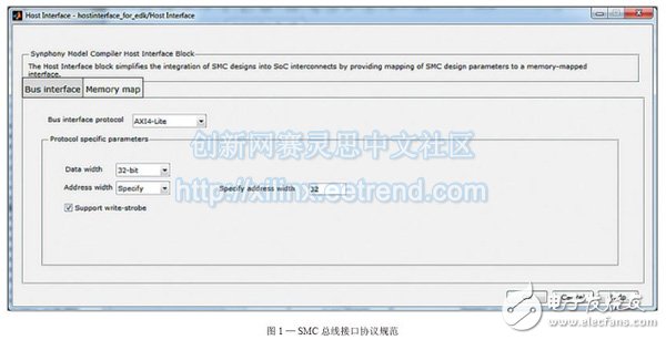
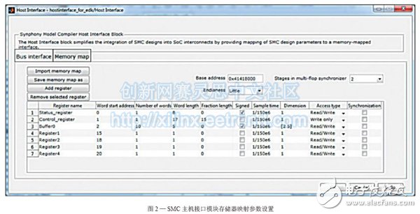
Step 1: Creating Peripherals with the SMC Library The first thing you need to do is to create an algorithm implementation of the peripherals using the SMC library module and verify functionality. The SMC host interface module is then configured according to two factors: the configuration data of the algorithm portion (which defines the memory map parameters) and the system's interconnect bus protocol (which defines the bus interface parameters). The host interface module is then associated with the peripheral algorithm portion. Some parameters of the host interface module (such as bus interconnect, address width and base address) will depend on your target platform. For example, we chose the Xilinx Virtex®-7 FPGA as the platform and chose AXI4-Lite as the bus interface. The platform has certain restrictions on the address width, base address and address space of each peripheral. The address width must be 32 bits, and the base address must be a multiple of 4K bytes, and the minimum available address space is 4K bytes. Figures 1 and 2 are views of how the bus interface protocol and memory mapping are configured using the host interface module.
For ease of integration, although not mandatory, it is strongly recommended that the bus interface port in the SMC model follow the naming conventions required by Xilinx EDK. Please add "S_AXI_" to the standard AXI4-Lite interface signal name. For example, the address signal of the AXI address writing channel (AWADDR) should be named S_AXI_AWADDR. If the signal does not follow the AXI4-Lite naming convention, it is possible to map the port name to the AXI4-Lite signal name when the peripheral is imported into the Xilinx EDK. Also, don't use uppercase letters in Simulink model names because EDK does not support peripherals with uppercase letters in their names.
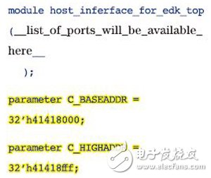
After adding, configuring, and connecting host interface modules, you can use SMC's RTL generation engine to generate RTL for peripherals. Specify target devices, implementation parameters, and optimization limits in the SMC UI to enable the RTL generation engine to generate optimized hardware for the target device. Two virtual parameters are added to the top-level RTL generated by the SMC (the top-level RTL is generally VHDL), and are named: "C_BASEADDR" and "C_HIGHADDR". The default value is assigned to the base address of the memory map space and the maximum address of the memory map space according to IP requirements. This step must ensure that the EDK recognizes the memory mapped address space of the peripheral. An example of a top-level Verilog RTL for SMC-generated designs is shown below, with two parameters to highlight.
For ease of integration, although not mandatory, it is strongly recommended that the bus interface port in the SMC model follow the naming conventions required by Xilinx EDK.
Step 2: Import peripherals into Xilinx EDK and integrate them. The next step is to import peripheral hardware into EDK's Xilinx Platform Studio (XPS) and make the necessary connections in the system (bus interface ports and functions) port). In this example, we have created a basic system with a MicroBlaze processor, a module RAM (BRAM) for storing executable software, a local memory bus (LMB), an AXI4-Lite interconnect, and a MicroBlaze debug module.
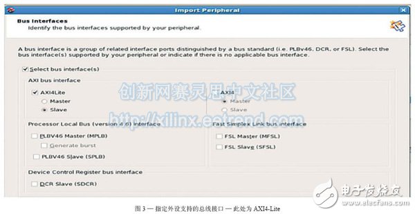
Select the "Create or import peripherals" option under the hardware directory of the XPS GUI. This will open the Create and Import Peripheral Wizard. Select the "Import existing peripherals" option in the wizard. Then specify the storage path, design name, and file type (HDL) of the peripheral. Now add all RMC files generated by SMC. After successfully compiling the RTL, you need to identify the bus interface supported by the peripheral, ie the AXI4-Lite slave interface, as shown in Figure 3.
Select the AXI4-Lite port of the peripheral in the next page of the wizard and map it to the standard AXI4-Lite port so that the EDK can connect to the bus interface. If the bus interface port name defined in the SMC model matches the standard bus port name, the EDK will automatically map the port (see Figure 4).
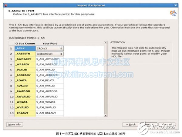
If the port names do not match, you may want to override the automatic mapping, as shown by the AXI4-Lite clock (Clk-Div3) and reset (GlobalReset) signals.
Then, according to the C_BASEADDR and C_HIGHADDR parameters of the RTL inserted in the first step, specify the register space base address and the upper address. Deselect the memory space option because the host interface module has an addressable configuration register space. However, in the next page, you should keep the default properties of the RTL parameters unchanged to ensure that they are consistent with the parameters specified in the host interface module.
The title of the next page is "Port Properties". Here you must specify the clock attribute, or a reset on all other clocks or a reset in the design. Please click on “Finish†on the next page to add peripherals to the XPS project. The SMC peripheral has now been successfully imported into XPS. You can view by
The /pcores folder (where XPS creates a directory using the peripheral name) verifies that it was successful. Browse the directory and check if the RTL file is imported correctly.
In addition, XPS will also create a directory alongside the HDL directory called "Data." This data directory contains the microprocessor peripheral description (*.mpd) file and associated peripheral parameters and their port information. Check to see if the SIGIS = CLK and SIGIS = RST parameters are already defined on the clock and reset ports. If not defined, you will need to edit the *.mpd file and add the definition manually. Figure 5 is an example of a file with these parameters added.

Intelligent charging logo and fast charging: This 100 port USB charger automatically identifies the current signal and performs the current output according to the device restriction. The device is limited to intelligent and secure. Just plug in, no driver or software is required. The latest generation of USB hub controller, the maximum charging output of each USB port 3.5A. Single -port supports fast charging to save your time and energy. 100 % security charging: This 100 port USB charging station built -in smart chip is to prevent voltage from exceeding the current and overload. Reasonable cooling holes can effectively dissipate heat to prevent excessive excessiveness. Excessive charging protection, when these devices are fully charged, they will automatically convert to small charges flowing current, and the battery saturation rate is 99 %.
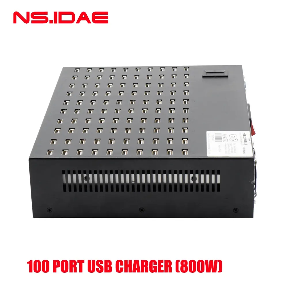
100 Port Usb Charger,100 Port Usb Wall Charger,Multi Port Usb Hub Charger,100 Port Usb Charging Station
shenzhen ns-idae technology co.,ltd , https://www.best-charger.com
